Method of reducing packet loss by resonance identification in communication networks

a technology of resonance identification and communication network, applied in data switching networks, frequency-division multiplexes, instruments, etc., can solve problems such as inability to achieve, and increase the load on the network

Inactive Publication Date: 2009-06-23
RIVERBED TECH LLC
View PDF50 Cites 11 Cited by
  • Summary
  • Abstract
  • Description
  • Claims
  • Application Information

AI Technical Summary

Problems solved by technology

This ideal case, however, requires that all nodes somehow know the timing and rate of packets that will be presented to the network with no overload and no delay in acquiring this information; a situation which is not possible.
This only serves to worsen the situation.
As more and more packets are retransmitted, the load on the network grows and more and more nodes become saturated.
Indeed, it has been shown that even where queue lengths are allowed to be infinite, congestion can occur.
One reason that this is true is that packets are often coded with an upper bound on their life, thus causing expired packets to be dropped and retransmitted, adding to the already overwhelming volume of traffic within the network.
Such non-TCP techniques require the transmission of some control information between the nodes and this overhead itself tends to limit the available network bandwidth for data traffic.
Even these “good” congestion control processes, however, are not good enough.
Studies of traffic flow across the Internet show that bandwidth of the various communication links is underutilized even in the presence of congestion.
That is, even though excess capacity exists on the communication links that couple various nodes of the Internet to one another, packets are still being dropped within the network.
One reason that conventional congestion control processes have failed in this fashion is that such processes do not take into account the true nature of network traffic.

Method used


Image

  • Method of reducing packet loss by resonance identification in communication networks
  • Method of reducing packet loss by resonance identification in communication networks
  • Method of reducing packet loss by resonance identification in communication networks

Examples


Embodiment Construction

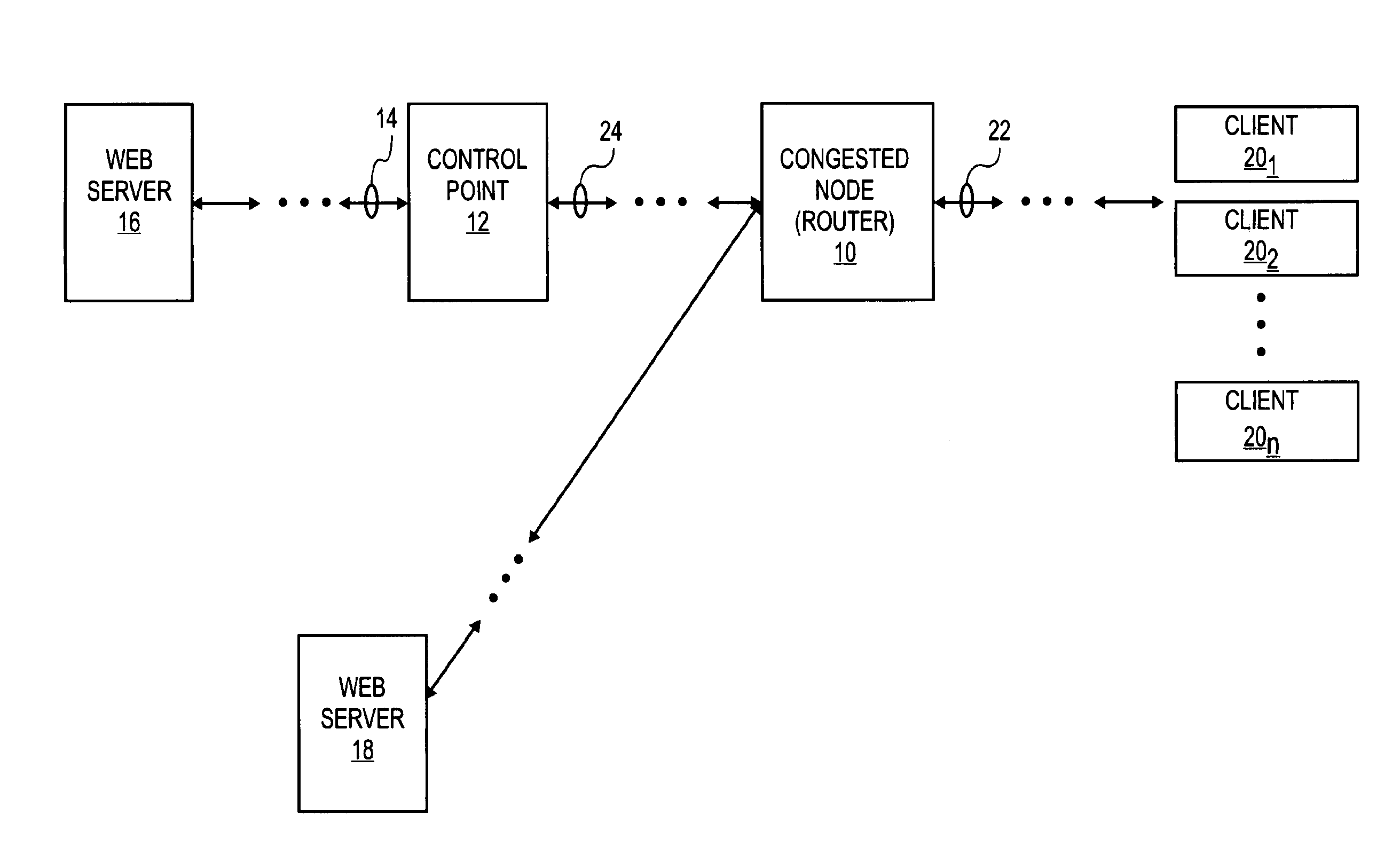
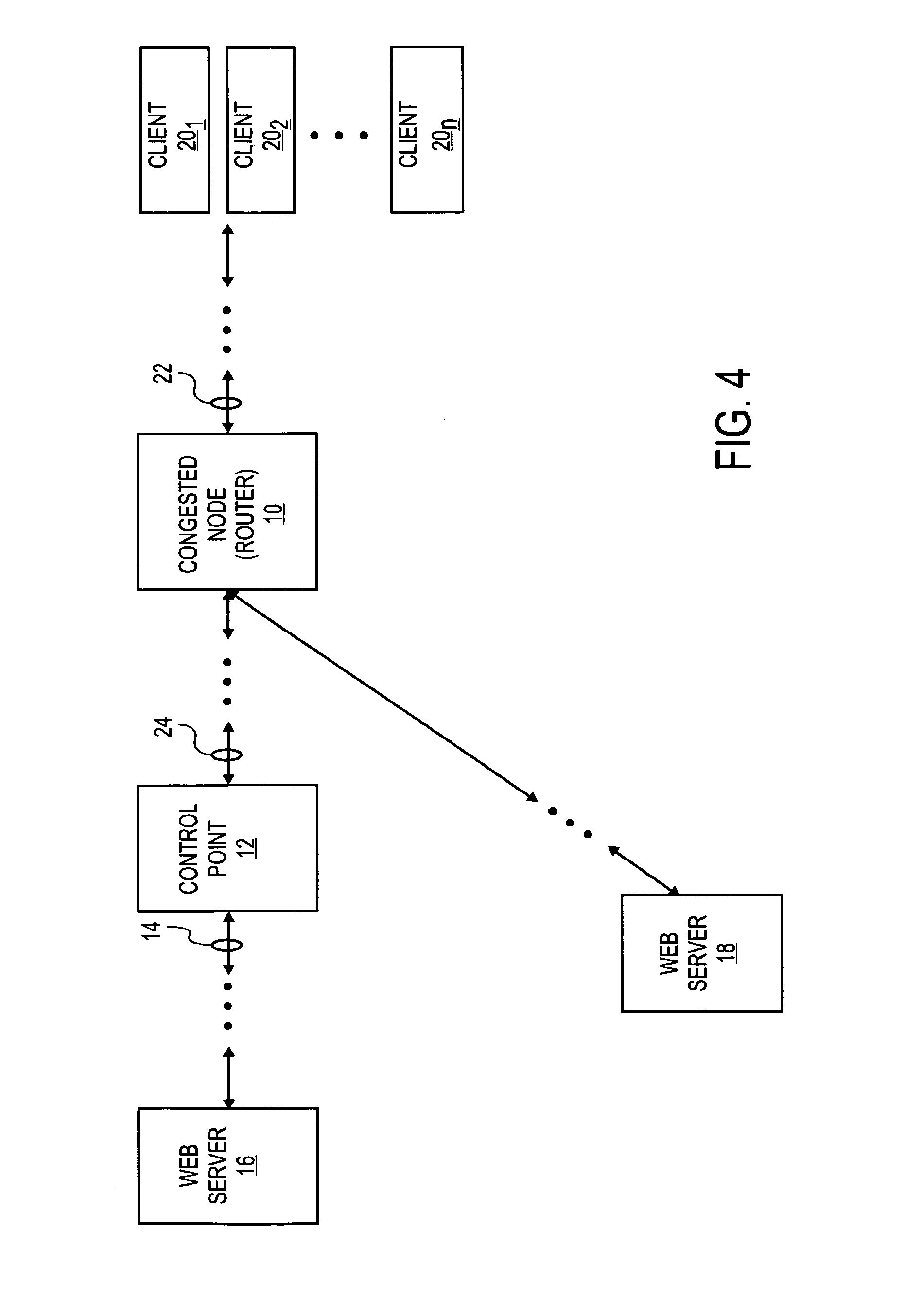
[0015]A scheme for operating control nodes of a computer or other communication network that utilizes packet switching techniques is disclosed herein. As discussed in greater detail below, the present scheme allows for control nodes to be operated at points that correspond to instances of minimum packet loss (maximum throughput) for given network traffic conditions. These same control points also correspond to instances of minimum fetch time, thus allowing for improved user experience (i.e., by reducing the time needed to download content from a content site). Although discussed with reference to certain illustrated embodiments, upon review of this specification, those of ordinary skill in the art will recognize that the present scheme may find application in a variety of systems. Therefore, in the following description the illustrated embodiments should be regarded as exemplary only and should not be deemed to be limiting in scope. It should also be noted that as used herein the te...


PUM


Abstract

A control node of a communication network is operated at a packet bandwidth determined according to observations of performance metrics of the network at the control point. These performance metrics may be one or more of throughput, average fetch time and packet loss. The control node is operated so as to set a control bandwidth to corresponding resonance points of the performance metrics. The resonance points are determined by scanning across a range of control bandwidths, until one or more of the performance metrics is / are optimized. The packet bandwidth is set by varying an inter-packet delay time over selected communication links at the control node.

Description

FIELD OF THE INVENTION[0001]The present invention relates to a scheme for operating a control node of a computer or other communication network that relies on packet switching techniques to transport information between nodes therein in order to reduce packet loss in the network.BACKGROUND[0002]Many communication networks, such as the Internet, rely on packet switching technologies (e.g., X.25, frame relay, asynchronous transfer mode, etc.) to transport variable or uniform blocks (usually termed packets or cells) of data between nodes. The term packet will be used herein to collectively refer to any such block of information. Such networks generally perform two major functions: routing and congestion control. The object of routing is to deliver, correctly and sometimes in sequence, the packets from a source to a destination. The object of congestion control is to maintain the number of packets within the network (or a region or sub-network thereof) below a level at which queuing del...

Claims


Application Information

Patent Timeline
Patent Type & Authority Patents(United States)
IPC IPC(8): H04L12/26
CPCH04L43/0864H04L47/10H04L47/22H04L47/25H04L47/283
Inventor DUONG-VAN, MINHWEN, HAN C.CRANE, MARKPAVEL, TOMAS J.
Owner RIVERBED TECH LLC
Why Eureka
Try Eureka