Electrical connector for connecting a plurality of printed circuits

a technology of printed circuits and connectors, applied in the direction of application, coupling device connection, diagnostic recording/measuring, etc., can solve the problems of circuits that require very long straight segments, circuits that require turns or very long segments, and waste significant materials

Active Publication Date: 2009-06-30
LIFESYNC
View PDF51 Cites 39 Cited by
  • Summary
  • Abstract
  • Description
  • Claims
  • Application Information

AI Technical Summary

Problems solved by technology

The cost of using flexible circuits depends on the distance and shape between the circuits to be connected.
Circuits that require turns or very long segments of straight lengths often waste significant material due to limitations on how the patterns can be laid out to maximize the use of material.
While such approach reduces the amount of substrate used, using hard connectors between discrete sections of circuits adds cost and complexity.
However, such a configuration restrictively grips the electrode thereby preventing any movement between the lead wire and the electrode.
Such a limitation leads to significant cable strain along the lead wire and the need to disengage and reattach the lead wires whenever the subject being monitored moves or the monitoring equipment is moved in a different orientation.
Many applications require that more than one electrode be used in sensing a physiological function and often, it is not practical to require each electrode be individually connected.
The use of individual leads risks entanglement and confusion between the wires.
Although a connector which may be rotated with respect to the electrode is much more easily adapted to the shape of a stud-type electrode in comparison to a tab-style electrode, the use of a plurality of individual wires to attach a subject to a monitoring device severely limits the mobility of the subject being monitored.
The comfort of the subject is compromised and the ability to monitor a physiological function while the subject is active is nearly impossible.
However, a single wire connection between the terminal edge and the monitoring device still requires that the subject be tethered such that mobility and comfort are still restricted.
Also, due to the fact that the electrode connections are integrated along a single chest patch, the placement of the electrodes upon the subject being monitored is fixed or substantially limited in order to correspond to the electrode connections defined in the chest patch.
Although limiting electrode placement may be beneficial in avoiding improper placement, the benefit is limited as the chest patch must still be properly placed on the chest in the first instance.
Although such a configuration provides much greater comfort and mobility to the subject being monitored, the costs of such an integrated chest patch are much higher and thus would not be disposable.
Although the circuit ends are pressed into overlapping contact between the two flat, top and bottom surfaces of the connector and are held in place by a snap-fit mating mechanism at the aperture running through the centering axis of the connector, the circuits are not pressed so tightly together that they cannot be rotated easily.

Method used


Image

  • Electrical connector for connecting a plurality of printed circuits
  • Electrical connector for connecting a plurality of printed circuits
  • Electrical connector for connecting a plurality of printed circuits

Examples


Embodiment Construction

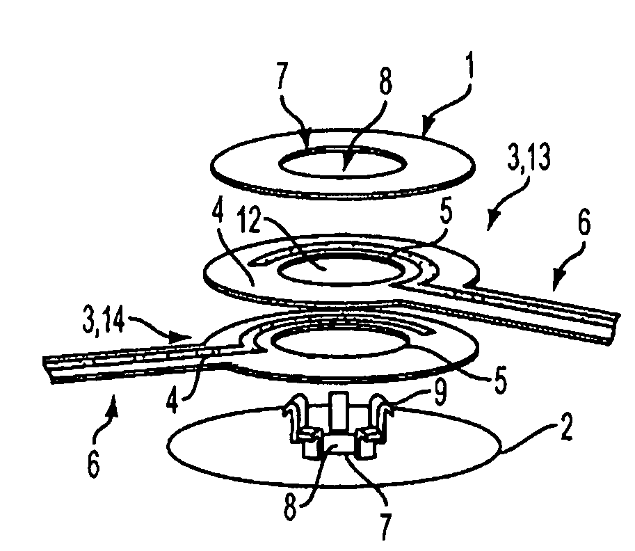
[0059]The present invention is an articulated electrical connector used to provide an electrical connection between printed circuits. The circuits may be flexible, semi-flexible or rigid circuits. The connection may be made between two discrete parts or may be used to connect different sections of the same circuit.

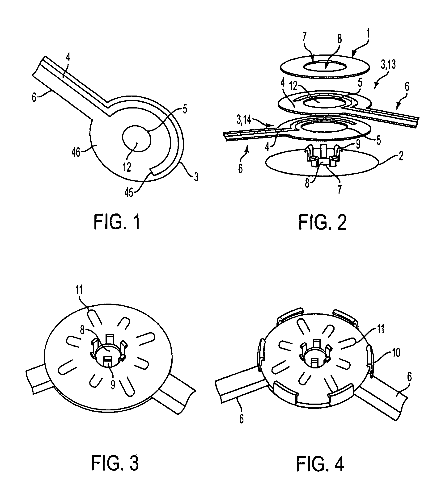
[0060]As shown in FIG. 1, at its simplest, the connector is nothing more than two or more of the illustrated exposed conductors 45 on a non-conductive backing 46 which are mated together and fastened to complete the connection. As shown in FIGS. 9A and 9B, the circuits may or may not have insulation 47 covering the traces in regions where they do not meet. Suitable fasteners include conductive and non-conductive adhesives, tapes, rivets, clips, clamps, interlocking fit, friction fit, or outer or intermediate housings or any suitable means to hold the two or more circuits together as may be required to maintain or prevent electrical contact as required by the particular cir...


PUM


Abstract

The present invention comprises an inexpensive and simple means for electrically and mechanically connecting a plurality of printed circuits together. The present invention also comprised embodiments where the printed circuits can be moved relative to each other without breaking the electrical contact between them. Yet another embodiment contemplates a means for joining two linear printed circuits to make a longer circuit. In yet another embodiment, the printed circuits and connections are used to make an inexpensive, reliable electrical harness for contacting a patient-worn sensor to a patient monitor such as an ECG monitor.

Description

[0001]This application claims priority to corresponding U.S. Provisional Application No. 60 / 771,742, filed on Feb. 9, 2006, which incorporates U.S. application Ser. No. 10 / 439,356, filed on May 16, 2003, U.S. application Ser. No. 11 / 077,934, filed on Mar. 11, 2005, U.S. application Ser. No. 11 / 105,230, filed on Apr. 12, 2005, U.S. application Ser. No. 11 / 105,231, filed on Apr. 12, 2005, U.S. application Ser. No. 11 / 105,232, filed on Apr. 12, 2005, U.S. application Ser. No. 09 / 998,733, filed on Nov. 30, 2001, and U.S. application Ser. No. 09 / 908,509, filed on Jul. 17, 2001, now U.S. Pat. No. 6,611,705, the disclosures and contents of which are expressly incorporated herein by reference.BACKGROUND OF THE INVENTION[0002]Flexible circuits are widely used in the electrical arts to make electrical connections between separate pieces of hardware. Such circuits are generally made from an electrically inert substrate such as polyester film upon which are printed electrically conductive trace...

Claims


Application Information

Patent Timeline
Patent Type & Authority Patents(United States)
IPC IPC(8): H01R12/00H05K1/00
CPCA61B5/04085A61B5/04286H01R12/61H01R12/616H01R23/667H01R35/04H05K3/365A61B2562/227H01R9/096H01R13/627H05K1/118H05K2201/058H05K2201/09063H05K2201/10053H05K2201/10598H01R12/52H01R12/78Y10S439/909A61B5/282A61B5/303
Inventor GOBRON, STEPHANE
Owner LIFESYNC
Why Eureka
Try Eureka