Check patentability & draft patents in minutes with Patsnap Eureka AI!

Non-contact tonometer

a tonometer and non-contact technology, applied in the field of tonometers, can solve the problems of low reliability of measurement, weakened output of photo sensors, and inability of photo sensors to receive light flux normally, and achieve the effect of stably making determinations with high reliability

Inactive Publication Date: 2009-06-30
CANON KK
View PDF8 Cites 6 Cited by
  • Summary
  • Abstract
  • Description
  • Claims
  • Application Information

AI Technical Summary

Benefits of technology

[0009]An object of the present invention is to eliminate the above-described problems and to provide a non-contact tonometer that can stably make determination with high reliability irrespective of variations in the reflectance of eyes to be examined.

Problems solved by technology

In the case that alignment is displaced due to a failure in fixation of the eye to be examined upon measurement or in the case that eyelashes overlap the measurement field, the photo sensor cannot receive a light flux normally.
In that case, the output of the photo sensor is weakened and reliability of the measurement becomes low even when a peak of the deformation signal is detected.
Consequently, in the case that an eye having a high cornea reflectance is examined, there is a risk that the output from the photo sensor will not becomes lower than the reference value even if misalignment or the like occurs at the time of measurement and the output is weakened.
In other words, there is a risk that the measurement result could be determined as normal in spite that the reliability of the result is low in reality.
On the other hand, in the case that the reflectance of a cornea is low, since the output from the photo sensor is low, there is a risk that the output from the photo sensor will not becomes higher than the reference value and the measurement will be regarded as an error or the mark indicating low reliability will be annexed, in spite that the measurement has been normally performed.

Method used


Image

  • Non-contact tonometer
  • Non-contact tonometer
  • Non-contact tonometer

Examples


Embodiment Construction

[0019]In the following, the present invention will be specifically described based on an embodiment shown in the drawings.

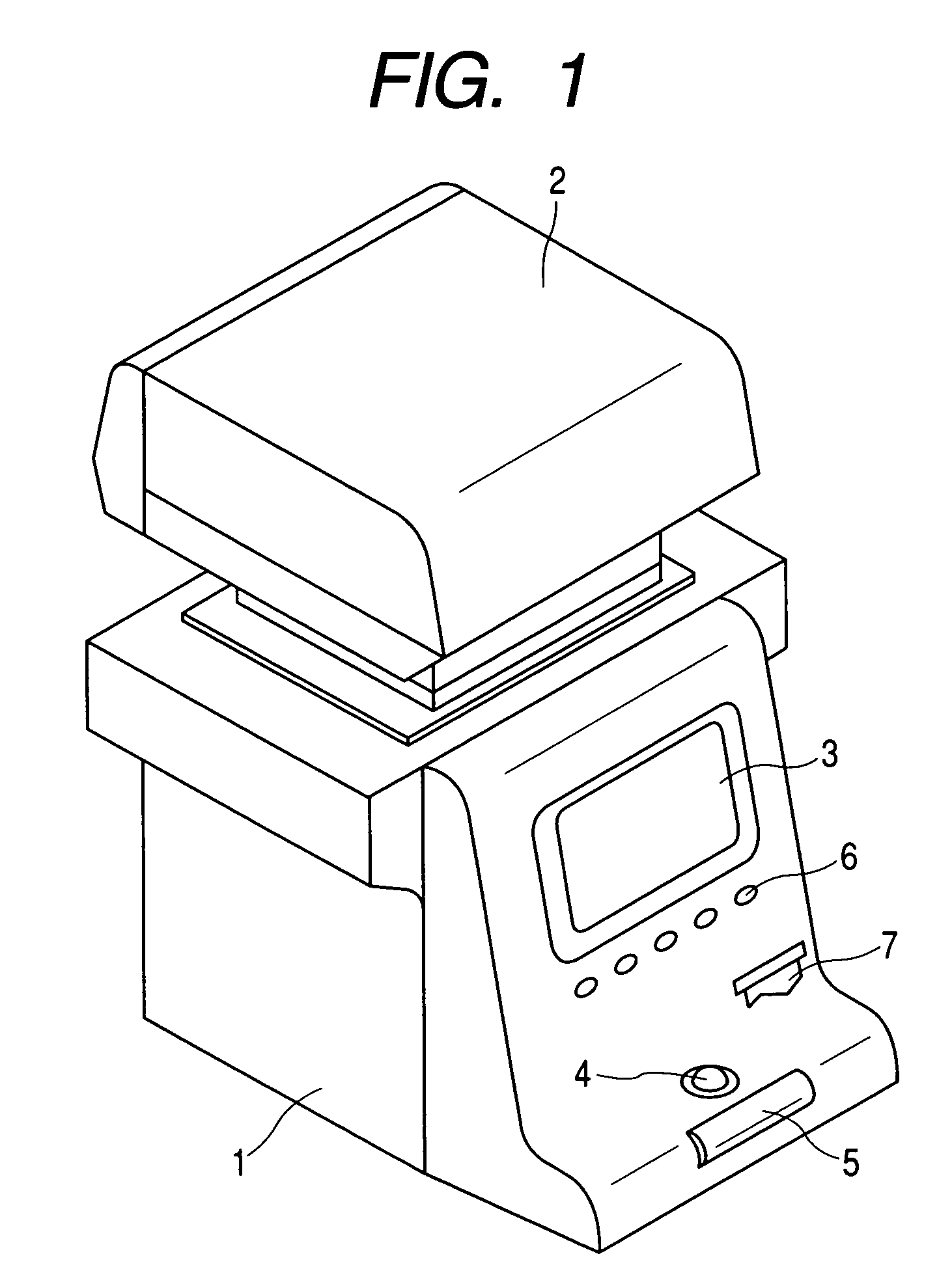
[0020]FIG. 1 shows the appearance of a non-contact tonometer. The non-contact tonometer is provided with a base 1 and a measuring portion 2 movably disposed on the base 1. On the side of the base 1 to be operated by an examiner (i.e. an operator), there is provided a monitor 3 on which measurement values and an eye to be examined etc. are displayed, a track ball 4 and a roller 5 used for roughly aligning the measuring portion 2 with the eye to be examined, a switch panel 6 in which a printing switch, a measurement starting switch and a selecting and setting switch etc. are arranged and a printer 7.

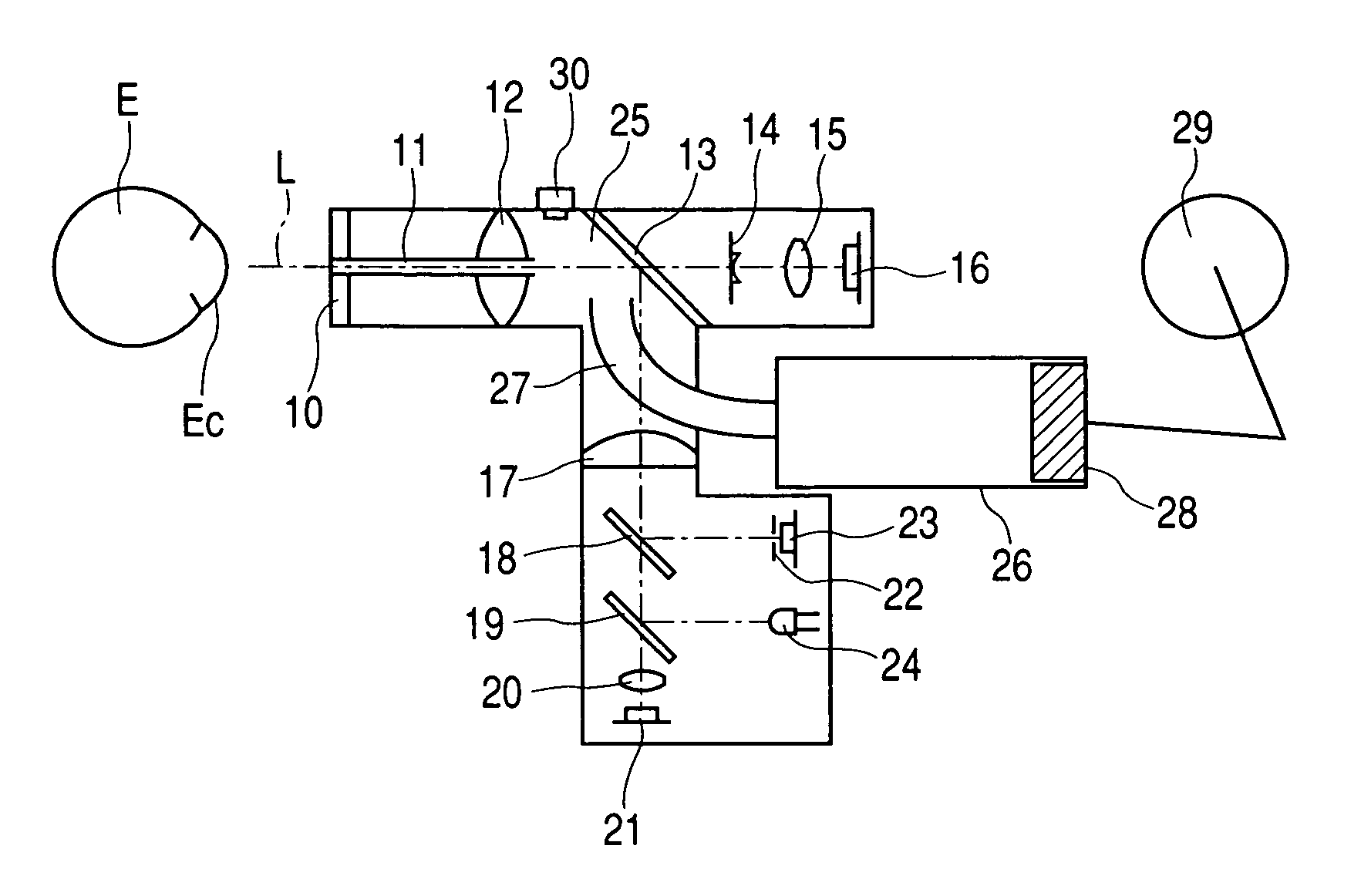
[0021]An examinee (i.e. a patient) should place his or her head on a head support portion (not shown) provided on the side opposite to the side to be operated by the examiner so that the eye to be examined is positioned in front of an objective portion of the measuring ...


PUM


Abstract

A non-contact tonometer changes a reference signal used for determining reliability of a signal indicating deformation of a cornea based on the reflectance of the cornea of an eye to be examined. Thus, the non-contact tonometer can perform stable measurement irrespective of the reflectance of the cornea of the eye to be examined.

Description

BACKGROUND OF THE INVENTION[0001]1. Field of the Invention[0002]The present invention relates to a non-contact tonometer used in an eye doctor's office etc.[0003]2. Related Background Art[0004]In a conventional non-contact tonometer, a piston is moved in a cylinder driven by rotation of a rotary solenoid to compress the air in the cylinder so that a compressed air is blown to a cornea of an eye to be examined (i.e. a patient's eye). At the same time measurement light is projected onto the cornea from a light source and reflection light from the cornea is received by a photo sensor or the like. Then, certain deformation of the cornea is detected by detecting a peak of the output signal from the photo sensor, and the internal pressure in the interior of the cylinder is measured. The measured pressure is converted to an intraocular pressure value.[0005]In the case that alignment is displaced due to a failure in fixation of the eye to be examined upon measurement or in the case that eye...

Claims


Application Information

Patent Timeline
IPC IPC(8): A61B3/16A61B13/00A61B3/00A61B3/10A61B3/14
CPCA61B3/165A61B3/16
Inventor MASAKI, TOSHIFUMI
Owner CANON KK
Features
  • R&D
  • Intellectual Property
  • Life Sciences
  • Materials
  • Tech Scout
  • Unparalleled Data Quality
  • Higher Quality Content
  • 60% Fewer Hallucinations
Learn More