
Apparatus and method for preparing a spinal implant surgical site for receiving a spinal fusion implant

a spinal fusion and implant technology, applied in the field of surgical joining of bone bodies, can solve the problems of increasing costs, adding trauma to the procedure, and not being practical for certain joints, and achieves the effects of preventing lateral movement, enhancing frictional stabilization, and imparting a degree of lateral stabilization

Inactive Publication Date: 2009-06-30
MIDCAP BUSINESS CREDIT +2
View PDF47 Cites 10 Cited by
  • Summary
  • Abstract
  • Description
  • Claims
  • Application Information

AI Technical Summary

Benefits of technology

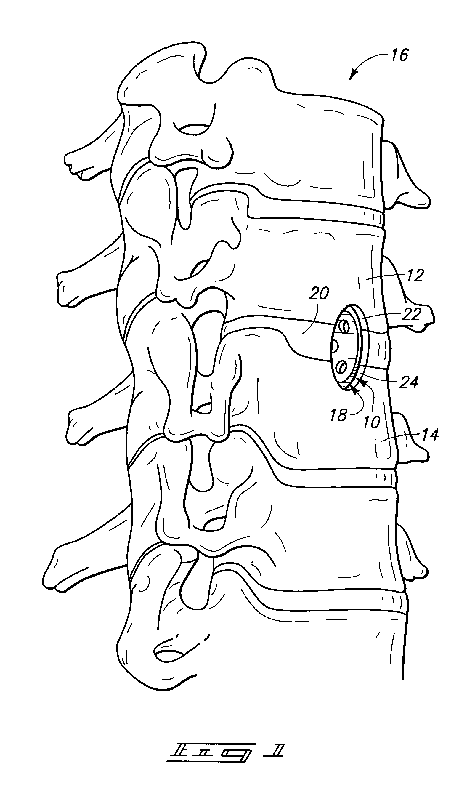
[0017]In accordance with one aspect of the invention, a bone joining implant comprises a tubular body having an open leading end, an open trailing end, and a central aperture; the open leading end communicating with the central aperture and configured to entrap a bone projection from each of a pair of adjacent bone bodies being joined together. The bone projection is integrally formed from each bone body being joined, and the implant houses bone graft material therein. The bone projections and bone graft material cooperate to enhance arthrodesis. Such implant directly and instantly stabilizes adjacent bone bodies by entrapping the bone projections.
[0019]In accordance with a third aspect of the invention, a tubular implant contains an aperture extending completely through the implant having a substantially continuous inner diameter which facilitates x-ray evaluation of bone healing within the implant, following implantation and arthrodesis. Particularly, such aperture facilitates evaluation extending in a direction along the axis of the tubular implant, generally in an anterior to posterior direction.
[0021]In accordance with a fifth aspect of the invention, a tubular implant includes a tubular body having an oblique outer surface and a cylindrical inner surface that is configured to be received in conforming implantable relation with a pair of bone bodies that are formed from a single cylindrical cut taken between adjacent bone bodies. Upon distraction, the cylindrical cut forms an obliquity between the adjacent bone bodies which conforms in substantially compliant fit-up with the oblique outer surface of the tubular implant. Such conforming fit-up increases frictional stabilization between adjacent bone bodies by generating a larger contact surface area therebetween. Furthermore, the oblique outer surface mates with such bone bodies in a manner that imparts a degree of lateral stabilization so as to prevent lateral movement at the adjoining interfaces.
[0022]In accordance with a sixth aspect of the invention, a tubular implant is provided with an open leading end and a central aperture in a manner to entrap intact bone projections extending from each of a pair of adjacent bone bodies. Such entrapment provides immediate, or instant, fixation between the adjacent bone bodies in a manner that caters to retention of the local bone bodies via the intact bone projections. Furthermore, bone graft material, or chips, are provided within the interior of the tubular implant so as to provide osteogenic material that is placed inside the implant. Such osteogenic material is preferably generated during preparation of the bone beds, which eliminates the need to perform additional surgeries for obtaining foreign bone graft material from other locations on a patient, or from another patient.

Problems solved by technology

However, these techniques are not practical for certain joints such as joints formed between spinal vertebrae.
However, a second surgical procedure must be performed to extract or harvest the dowel of bone, substantially adding trauma to the procedure, increasing costs, as well as increasing the threat of infection to the patient.
However, the original Bagby implant relies completely upon stretch of the annulus to stabilize the vertebrae during bone remodeling and fusion.
However, the threads per se of the implant do not function as a fastener to fix together the adjacent vertebral bodies.
Several additional problems result from the provision of threads on a cylindrical fusion implant.
One problem results in that threads take up additional space which makes implantation in areas having limited anatomical space very difficult, such as in the posterior approach in the lumbar spine.
Additionally, the threads effectively make the wall thickness greater which further separates bone provided inside the implant with bone provided outside the implant, which can delay initial bone union.
Where complete stabilization does not occur instantaneously upon implantation, motion can disrupt the ingrowth of delicate blood vessels.
Disruption of the vessels then restricts or even prevents bone healing therebetween.
The same problem occurs with any of the above-mentioned implant techniques, including the threaded techniques of Otero-Vich and Michelson.
Even when the annulus is completely on stretch, the threads per se of these constructions do not function in the manner of conventional screws, extending through one object and into another.
Furthermore, the presence of threads requires the implant to be screwed in place via a torquing process, instead of tapping the implant directly into position.
Also, when the implant is used to arthrodese and change angulation, a healthy annulus cannot be totally corralled to be placed on stretch.
As a result, there is no form of stabilization or fastening between bone bodies sufficient to enable the occurrence of arthrodesis therebetween when the annulus is weakened or inadequate.
However, such design requires the preparation of bone beds that are engaged in interlocking relation with a bone bed engaging portion provided by such undercut portions.
However, such procedure does not always impart sufficient distraction and takes time and space to implement.
However, such design is formed from several discrete components that are movably fastened together and which are susceptible of loosening and misadjusting within a patient.

Method used


Image

  • Apparatus and method for preparing a spinal implant surgical site for receiving a spinal fusion implant
  • Apparatus and method for preparing a spinal implant surgical site for receiving a spinal fusion implant
  • Apparatus and method for preparing a spinal implant surgical site for receiving a spinal fusion implant

Examples


Embodiment Construction

[0051]This disclosure of the invention is submitted in furtherance of the constitutional purposes of the U.S. Patent Laws “to promote the progress of science and useful arts” (Article 1, Section 8).

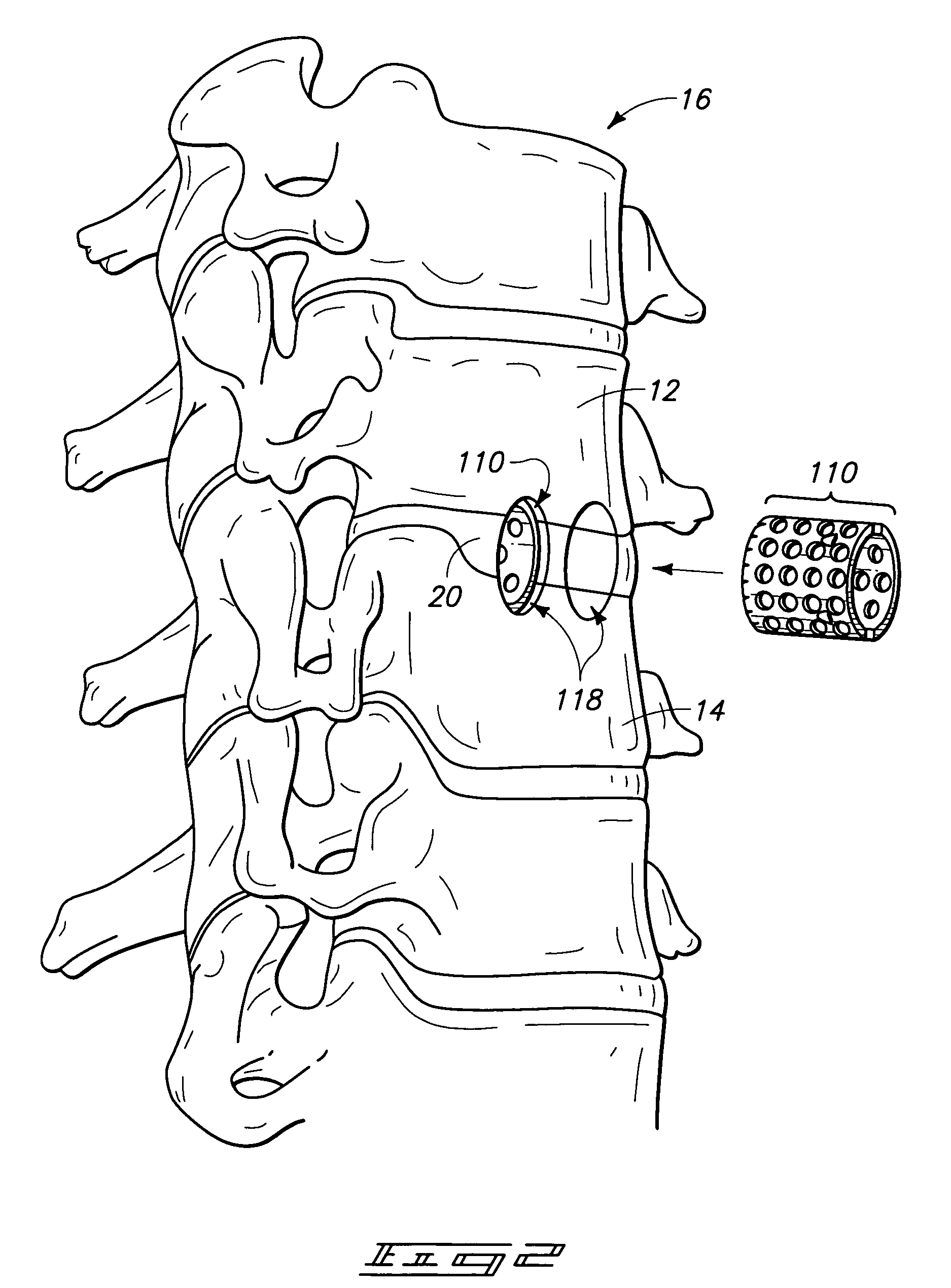
[0052]A preferred embodiment bone joining implant in accordance with the invention is first described with reference to FIGS. 1, 12-18 and 21-25. Such an implant is described further below with respect to an open-ended vertebral interbody implant having instant fixation in the form of a leading open end and self-distraction features in the form of a cylindrical inner surface and an oblique outer surface. The fixating and self-distracting implant is designated in FIGS. 1, 12-18 and 21-25 generally with reference numeral 10. An alternative implementation comprising a pair of somewhat smaller sized implants 110 are depicted in FIG. 2. Yet another alternative implementation comprises a substantially cylindrical tubular implant 210 depicted in FIGS. 26 and 27.

[0053]As shown in FIGS. 1, 12-18 a...


PUM


Abstract

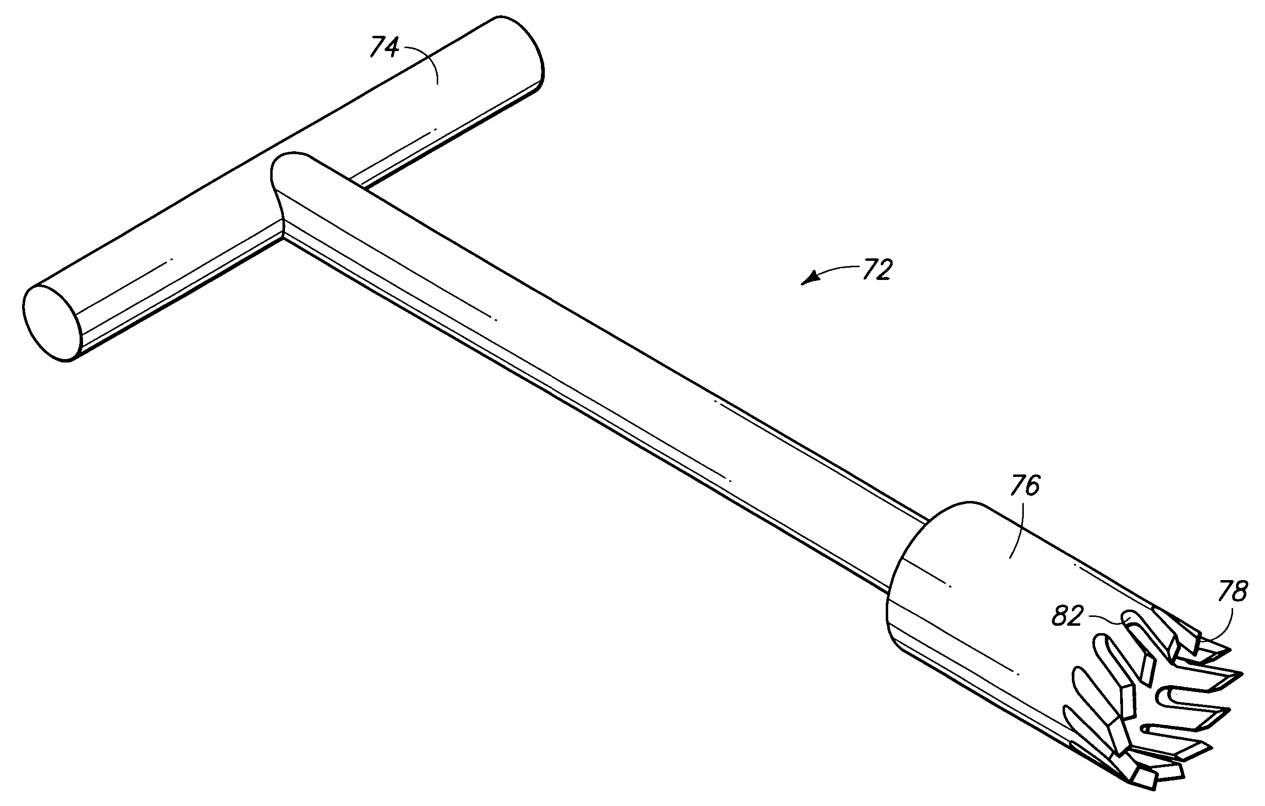
An apparatus is provided for preparing a spinal implant surgical site for receiving a spinal fusion implant. The apparatus includes a drive shaft, a handle, and a hollow, cylindrical cutting body. The handle is carried by the drive shaft, the hollow, cylindrical cutting body is provided at a leading end of the drive shaft. The cylindrical cutting body has an open leading end, a plurality of circumferentially spaced-apart cutting teeth provided on the open leading end, and a plurality of circumferentially spaced-apart gullets each provided between an adjacent pair of the cutting teeth. A method is also provided.

Description

RELATED PATENT DATA[0001]This continuation application claims the benefits of U.S. patent application Ser. No. 10 / 775,837, which was filed Feb. 9, 2004, now abandoned entitled “Bone Joining Implant With Retaining Tabs”, which in turn was a continuation of U.S. patent application Ser. No. 10 / 039,384, filed Dec. 31, 2001, and issued Feb. 10, 2004 as U.S. Pat. No. 6,689,167 B2, entitled “Method of Using Spinal Fusion Device, Bone Joining Implant, and Vertebral Fusion Implant”, which in turn was a divisional of U.S. patent application Ser. No. 09 / 179,920, filed Oct. 27, 1998, and issued Apr. 16, 2002 as U.S. Pat. No. 6,371,986, entitled “Spinal Fusion Device, Bone Joining Implant, and Vertebral Fusion Implant”, all of which are incorporated by reference herein.TECHNICAL FIELD[0002]This invention pertains to surgical joining of bone bodies, and more particularly to instruments, implants and methods for self-alignment, instant fixation, distraction, and staged bone fusion or arthrodesis o...

Claims


Application Information

Patent Timeline
Patent Type & Authority Patents(United States)
IPC IPC(8): A61F5/00A61D1/04A61F2/44A61B17/02A61B17/16A61B17/17A61F2/00A61F2/28A61F2/30A61F2/46
CPCA61B17/025A61B17/1637A61B17/1671A61B17/1757A61F2/446A61F2/4611A61B2017/0256A61F2/442A61F2002/2835A61F2002/30113A61F2002/30126A61F2002/30235A61F2002/30787A61F2002/3082A61F2002/3085A61F2002/30904A61F2002/4475A61F2002/448A61F2002/4627A61F2230/0006A61F2230/0008A61F2230/0069A61F2002/30593
Inventor BAGBY, GEORGE W.
Owner MIDCAP BUSINESS CREDIT
Learn More