
Multi-winding motor with reduced impedance unbalance

a multi-winding motor and impedance reduction technology, applied in the direction of dynamo-electric machines, synchronous generators, electrical apparatus, etc., can solve the problems of increasing cost, impractical motor drive system, impedance unbalance or fluctuation of n f-phase exciting windings, etc., and achieve the effect of improving the impedance unbalance of multi-phase exciting windings

Active Publication Date: 2009-06-30
SANYO DENKI CO LTD
View PDF12 Cites 9 Cited by
  • Summary
  • Abstract
  • Description
  • Claims
  • Application Information

AI Technical Summary

Benefits of technology

[0007]An object of the present invention is to provide a multi-winding motor of which impedance unbalance among a plurality of F-phase windings can be improved.
[0008]Another object of the present invention is to provide a multi-winding motor of which impedance unbalance among a plurality of F-phase windings can be improved, and of which the arrangement allows for easy winding.

Problems solved by technology

As motors have been increasing in capacity, the driving devices for motors are also becoming larger to accommodate power elements and transformers of larger capacity and size, resulting in increased cost and leading to an impractical motor drive system.
The inverters I1 and I2 are adapted to be supplied with power from a common DC power supply P. In the conventional multi-winding motors, however, impedance unbalance or fluctuation occurs among N F-phase exciting windings.
In this specification, the wording “impedance unbalance” means that a large difference in impedance is generated among a plurality of exciting windings.
When a motor is driven, a fluctuation is generated among the currents flowing through the N F-phase exciting windings, causing problems such as torque ripple, torque reduction, lowered efficiency, and deteriorated accuracy of positioning.
Conventionally, in order to attain balanced current, an unbalance compensation voltage is applied to balance the current based on the error in current signals flowing through each of three phase exciting windings.
However, the correction circuit has a limitation.
Therefore, it is required to improve the impedance unbalance, which is the primary cause thereof.

Method used


Image

  • Multi-winding motor with reduced impedance unbalance
  • Multi-winding motor with reduced impedance unbalance
  • Multi-winding motor with reduced impedance unbalance

Examples


first embodiment

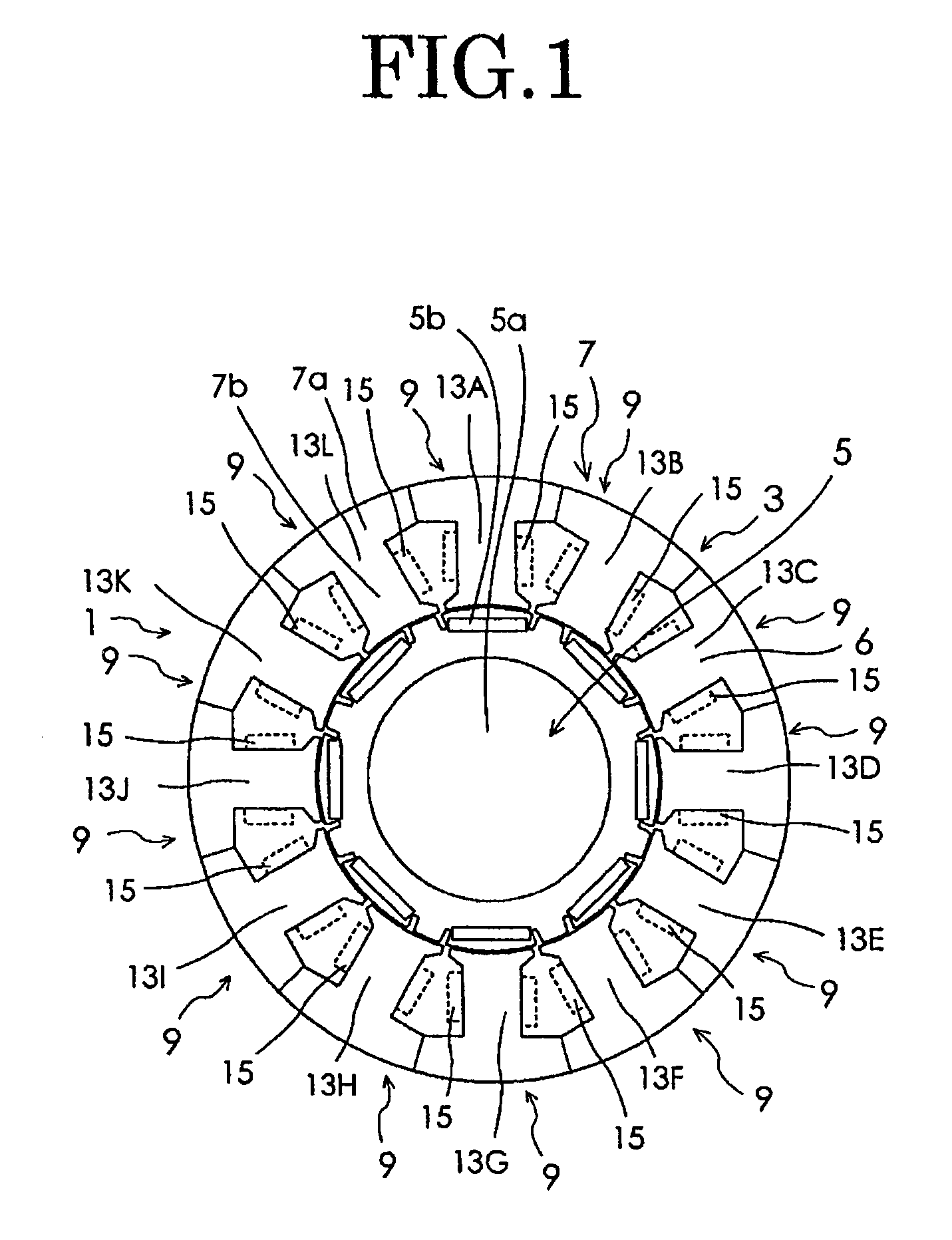
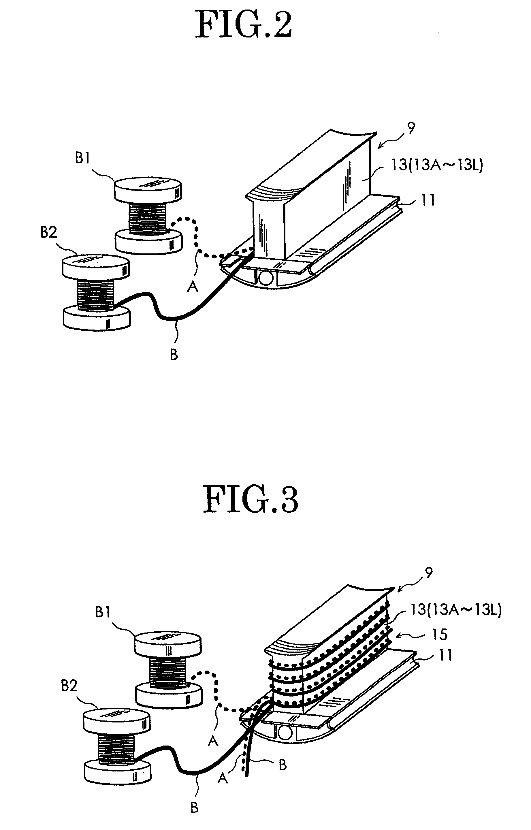
[0033]Now, the best mode for carrying out the present invention will be described in detail with reference to the accompanying drawings. FIG. 1 is a cross sectional view of a multi-winding motor according to the present invention. As shown in FIG. 1, a multi-winding motor 1 of the embodiment has a stator 3 and a rotor 5. The rotor 5 includes a rotor core 5a having a substantially columnar shape and eight plate-type permanent magnets 5b constituting magnetic pole sections, embedded in the vicinity of an surface portion of the rotor core 5a at regular intervals in a circumferential direction of the rotor core. The stator 3 includes a stator core 7. The stator core 7 is constructed from twelve divided cores 9 which are annularly arranged. The divided core 9 is integrally formed of a yoke constituent section 11 and a magnetic pole section 13 in a T-letter relation as shown in FIG. 2. Therefore, the stator core 7 has F×M (F and M are an integer of 2 or more) magnetic pole sections 13A-13...

second embodiment

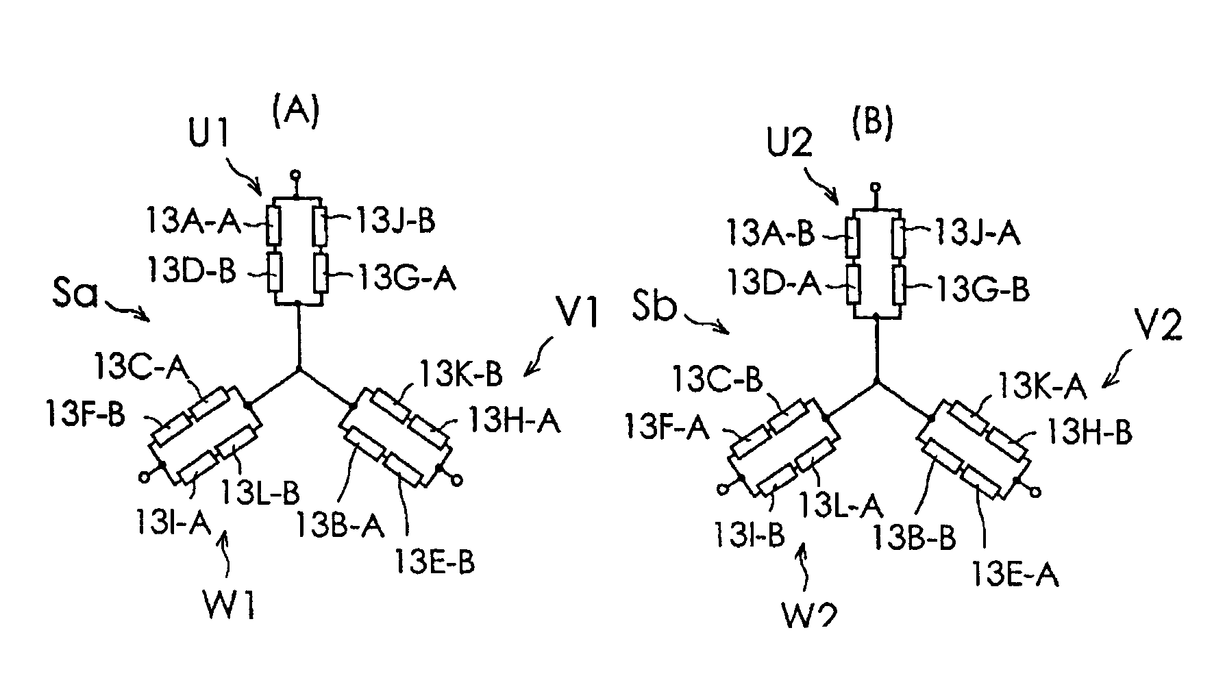
[0040]FIGS. 8(A) and (B) are illustrations showing a multi-winding motor of the present invention, in which discrete winding wirings A, B are connected in series with each other. As shown in FIG. 8(A), the first three-phase exciting winding Sa of the multi-winding motor according to the embodiment is constructed from an exciting winding U1, an exciting winding V1 and an exciting winding W1, which are star-connected with each other as shown in FIG. 8(A). The exciting winding U1 for one phase (U-phase) is constructed from four (M) discrete winding wirings A, B, A, B, which are selected one by one from the two (N) kinds of discrete winding wirings A, B provided at each of the four (M) magnetic pole sections (magnetic pole sections wound with the discrete winding wirings A, B of the U-phase winding sections 15) 13A, 13D, 13G, 13J selected from twelve (F×M) magnetic pole sections 13A-13L, and are connected in that order in series with each other. Specifically, the exciting winding U1 is ...

third embodiment

[0043]FIGS. 9(A) and 9(B) are illustrations showing how two (first and second) discrete winding wirings A, B of the three-phase exciting windings Sa, Sb are connected in a combination of series and parallel connections in a multi-winding motor according to the present invention.

[0044]FIGS. 9(A) and (B) are illustrations showing a multi-winding motor according to a third embodiment of the present invention, in which the discrete winding wirings A, B are connected with each other in a combination of series and parallel connections. The first three-phase exciting winding Sa of the multi-winding motor according to this embodiment is constructed from an exciting winding U1, an exciting winding V1 and an exciting winding W1, which are star-connected with each other as shown in FIG. 9(A). The exciting winding U1 for one phase (U-phase) is constructed from four (M) discrete winding wirings A, B, A, B, which are selected one by one from two (N) kinds of discrete winding wirings A, B provided...


PUM


Abstract

The present invention provides a multi-winding motor. Two three-phase exciting windings Sa, Sb are wound on each of the magnetic pole sections of divided cores 9. Two kinds of discrete winding wirings A, B are wound together with the same winding number onto each of the magnetic pole sections 13A-13L of the divided cores 9. Divided cores 9 wound with the discrete winding wirings A, B are annularly disposed, and are connected in parallel with each other so that the discrete winding wirings are arranged in the order of A, B, A, B . . . within the same connection, and the exciting windings are star-connected to construct two three-phase exciting windings Sa, Sb.

Description

BACKGROUND OF THE INVENTION[0001]1. Field of the Invention[0002]The present invention relates to a multi-winding motor having N F-phase exciting windings, which are independent of each other.[0003]2. Description of Related Art[0004]As motors have been increasing in capacity, the driving devices for motors are also becoming larger to accommodate power elements and transformers of larger capacity and size, resulting in increased cost and leading to an impractical motor drive system.[0005]As shown in Japanese Patent Application Laid-Open No. 1995-298685 (Patent Document 1), an attempt was made to reduce the size of the individual driving devices by connecting the driving devices (inverters or the like) separately to independent three-phase exciting windings of a multi-winding motor for synchronous driving.[0006]An example of such arrangement is described below in detail with reference to FIG. 13. A multi-winding motor M has two three-phase exciting windings Sa and Sb, which are indepen...

Claims


Application Information

Patent Timeline
Patent Type & Authority Patents(United States)
IPC IPC(8): H02K1/00
CPCH02K3/28
Inventor MIYASHITA, TOSHIHITOKOICHI, SHINTAROUMURATA, KAZUYOSHISAKAI, MASANORI
Owner SANYO DENKI CO LTD
Learn More