Thermal printhead
a printhead and thermal technology, applied in printing and other directions, can solve the problems of ink not being properly transferred, wrinkles in ink ribbons, etc., and achieve the effect of preventing wrinkles and preventing print failur
- Summary
- Abstract
- Description
- Claims
- Application Information
AI Technical Summary
Benefits of technology
Problems solved by technology
Method used
Image
Examples
first embodiment
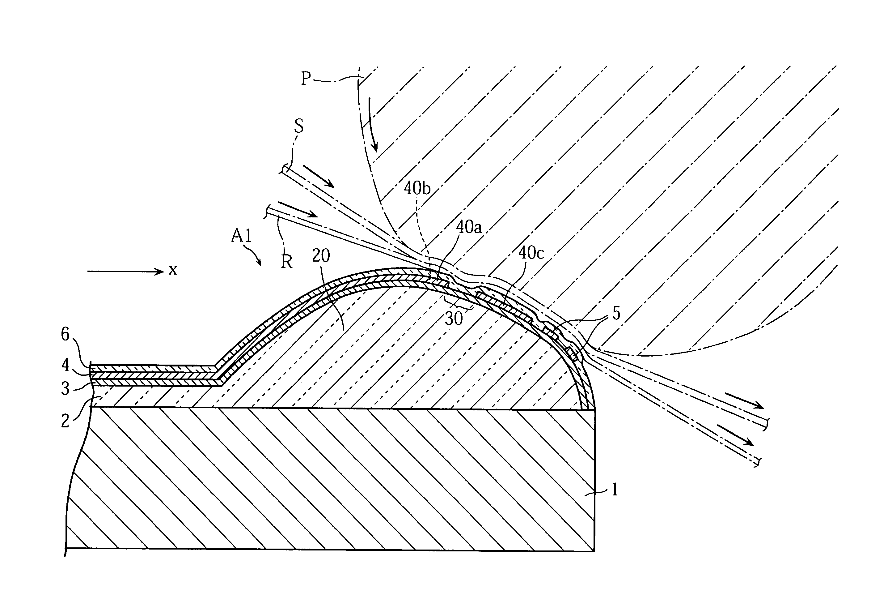
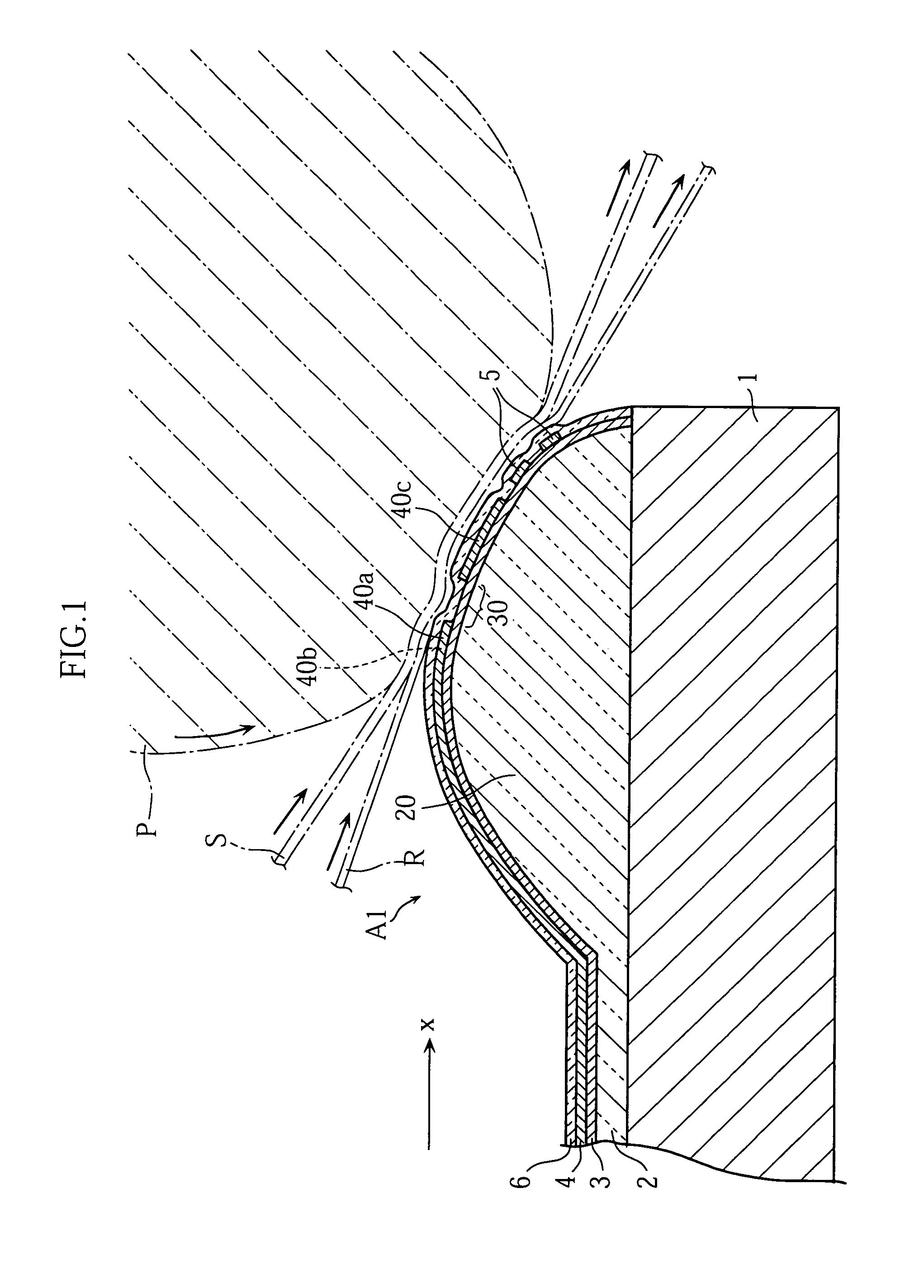
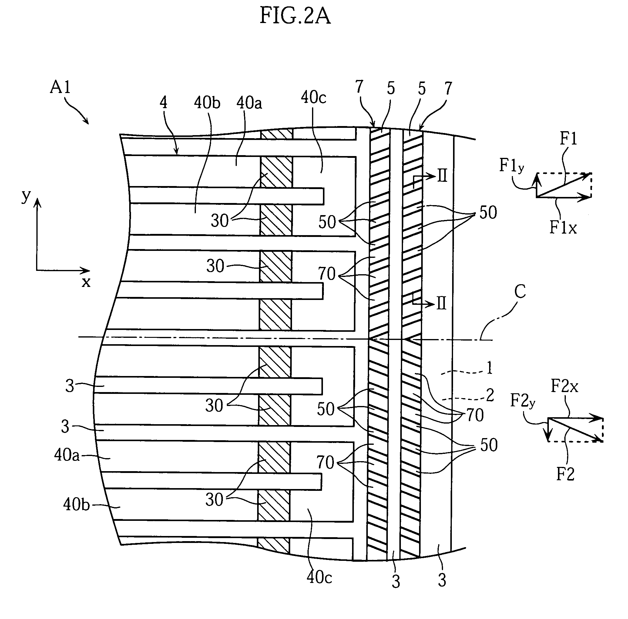
[0023]FIGS. 1, 2A and 2B show a thermal printhead according to the present invention. In FIG. 2A, the illustration of a protective layer indicated by the reference sign 6 in FIG. 1 is omitted.
[0024]As shown in FIG. 1, the thermal printhead A1 according to the first embodiment includes a substrate 1, a glaze layer 2, a resistor layer 3, an electrode layer 4, two strips of edge patterns 5, and a protective layer 6.
[0025]The thermal printhead A1 utilizes a platen roller P for printing. Specifically, a recording sheet S and a thermal ink ribbon R are supplied between the platen roller P and the thermal printhead A1, and printing on the recording sheet S is performed while transferring the recording sheet S and the ink ribbon R in a secondary scanning direction x. The surface portion of the platen roller P is made of rubber, for example, so that it deforms upon contact with the thermal printhead A1 due to the contact pressure.
[0026]The substrate 1 is a ceramic insulating substrate in the...
second embodiment
[0043]However, each of the projections 70 serves to guide the ink ribbon R in the primary scanning direction y, and when a force to shrink the ink ribbon R in the primary scanning direction y toward the center line C is generated in transferring the ink ribbon R, a resisting force against such a force is generated at each of the projections 70. Therefore, in the second embodiment again, the formation of wrinkles in the ink ribbon R is prevented.
[0044]As will be understood from the second embodiment and the first embodiment, the formation of wrinkles of the primary scanning direction y in the ink ribbon R is effectively prevented whether or not the projections 70 of the inequality surface region 7 are inclined with respect to the center line C. Therefore, projections 70 inclined with respect to the center line C and those which are not inclined may be mixedly provided. The angle of inclination relative to the center line C may be different among the projections.
[0045]FIG. 4 shows a t...
third embodiment
[0051]For instance, the inequality surface region 7 on the downstream side of the third electrode portions 40c in the secondary scanning direction x may be formed without utilizing edge patterns 5. In a structure which does not include edge patterns 5 like the thermal printhead A2 of the third embodiment, the inequality surface region 7 may be provided by alternately forming projections and recesses at part of the protective layer 6. To reliably prevent the formation of wrinkles in the ink ribbon, it is preferable to make the area of the inequality surface region 7 as large as possible. However, the present invention is not limited thereto, and the area is not limited to be specified.
[0052]The pattern of electrodes of the thermal printhead is not limited. The present invention is also applicable to a thermal printhead which includes a common electrode with so-called comb-tooth portions. Moreover, the present invention is applicable to both of a thick-film thermal printhead and a thi...
PUM
 Abstract
Description
Claims
Application Information
 - R&D
- Intellectual Property
- Life Sciences
- Materials
- Tech Scout
- Unparalleled Data Quality
- Higher Quality Content
- 60% Fewer Hallucinations
Browse by: Latest US Patents, China's latest patents, Technical Efficacy Thesaurus, Application Domain, Technology Topic, Popular Technical Reports.
© 2025 PatSnap. All rights reserved.Legal|Privacy policy|Modern Slavery Act Transparency Statement|Sitemap|About US| Contact US: help@patsnap.com


