Real time optimization over a shared communication channel

a shared communication channel and real-time optimization technology, applied in the field of encoded signal transmission, can solve problems such as constant change, achieve the effect of reducing color information, improving audio video quality, and reducing video quality

Active Publication Date: 2009-06-30
CREATIVE TECH CORP
View PDF16 Cites 1 Cited by
  • Summary
  • Abstract
  • Description
  • Claims
  • Application Information

AI Technical Summary

Benefits of technology

[0027]The encoded audio data A is accorded the highest priority and the encoded error data C is accorded the lowest priority. The encoded audio data A alone will provide a minimum quality of audio at the client station. Encoded error data C, in addition, will improve the audio quality. Encoded audio data A is guaranteed delivery whereas some or all of the error data C may be discarded if there is not available bandwidth. User data B is accorded a priority lower than the encoded audio data A but higher than the encoded error data C. If there is not available bandwidth to deliver user data B once encoded audio data A has been delivered, the user data B will be delivered on the next available cycle. Thus, the available bandwidth is used efficiently.
[0044]With this arrangement, the encoded audio data may be guaranteed delivery to a client station so as to ensure at least a minimum audio quality at the client station. The encoded error data may be delivered to the client station only if there is available bandwidth. Otherwise, some or all of the encoded error data may be discarded. The more encoded error data that is delivered to the client station (and processed at the client station to generate the reconstructed audio signal), the higher the audio quality at the client station.
[0057]In one advantageous embodiment, the method further comprises the step of the client station receiving the encoded error data C. In that case, the method may further comprise the step of the client station decoding the encoded error data C to generate decoded error data. The step of the client station generating the audio signal may comprise the client station generating the audio signal from the decoded audio data and the decoded error data. In that embodiment, the client station additionally uses some or all of the encoded error data C associated with the encoded audio data A to generate the audio signal, thereby resulting in an improved audio quality at the client station.
[0066]Thus, the host station is arranged to transmit the encoded audio data A and then, only if there is available bandwidth to transmit any user data B and then, only if there is available bandwidth, to transmit encoded error data C. The audio signal may be reconstructed from only the encoded audio data A; this will provide a minimum audio quality. Additionally, encoded error data C may be used to reconstruct the audio signal; this will improve the audio quality.
[0094]In an advantageous embodiment of the invention, the client station receiver is arranged to receive the encoded error data C. In that embodiment, the client station may further comprise a second decoder for decoding the encoded error data C, the second decoder being arranged to generate decoded error data. In that embodiment, the client station generator is preferably arranged to generate the audio signal from the decoded audio data and the decoded error data. In that embodiment, the client station uses the encoded error data C in addition to the encoded audio data A to generate the audio signal, thereby improving the audio quality.
[0108]The encoded video data A is accorded the highest priority and the encoded error data C is accorded the lowest priority. The encoded video data A alone will provide a minimum quality of video (with reduced color information) at the client station. Encoded error data C, in addition, will improve the audio video quality i.e. enhance the color. Encoded video data A is guaranteed delivery whereas some or all of the error data C may be discarded if there is not available bandwidth. User data B is accorded a priority lower than the encoded video data A but higher than the encoded error data C. If there is not available bandwidth to deliver user data B, once encoded video data A has been delivered, the user data B will be delivered on the next available cycle. Thus, the available bandwidth is used efficiently.

Problems solved by technology

This is particularly the case for wireless terminals relying on radio frequency (RF) signals emitted from a host station, as the environment may be quite volatile and the conditions can be constantly changing as the user moves from place to place.

Method used


Image

  • Real time optimization over a shared communication channel
  • Real time optimization over a shared communication channel
  • Real time optimization over a shared communication channel

Examples


Embodiment Construction

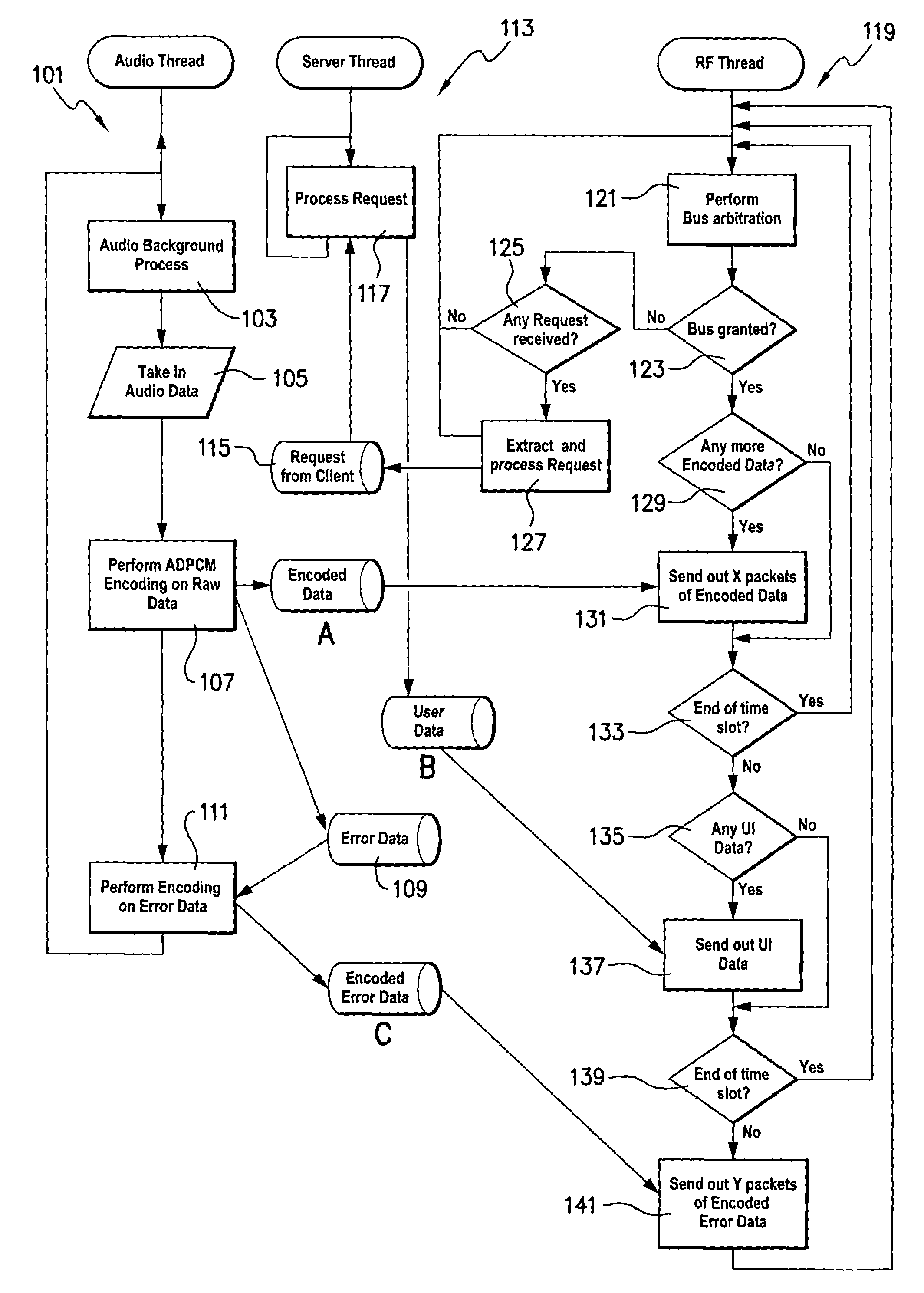
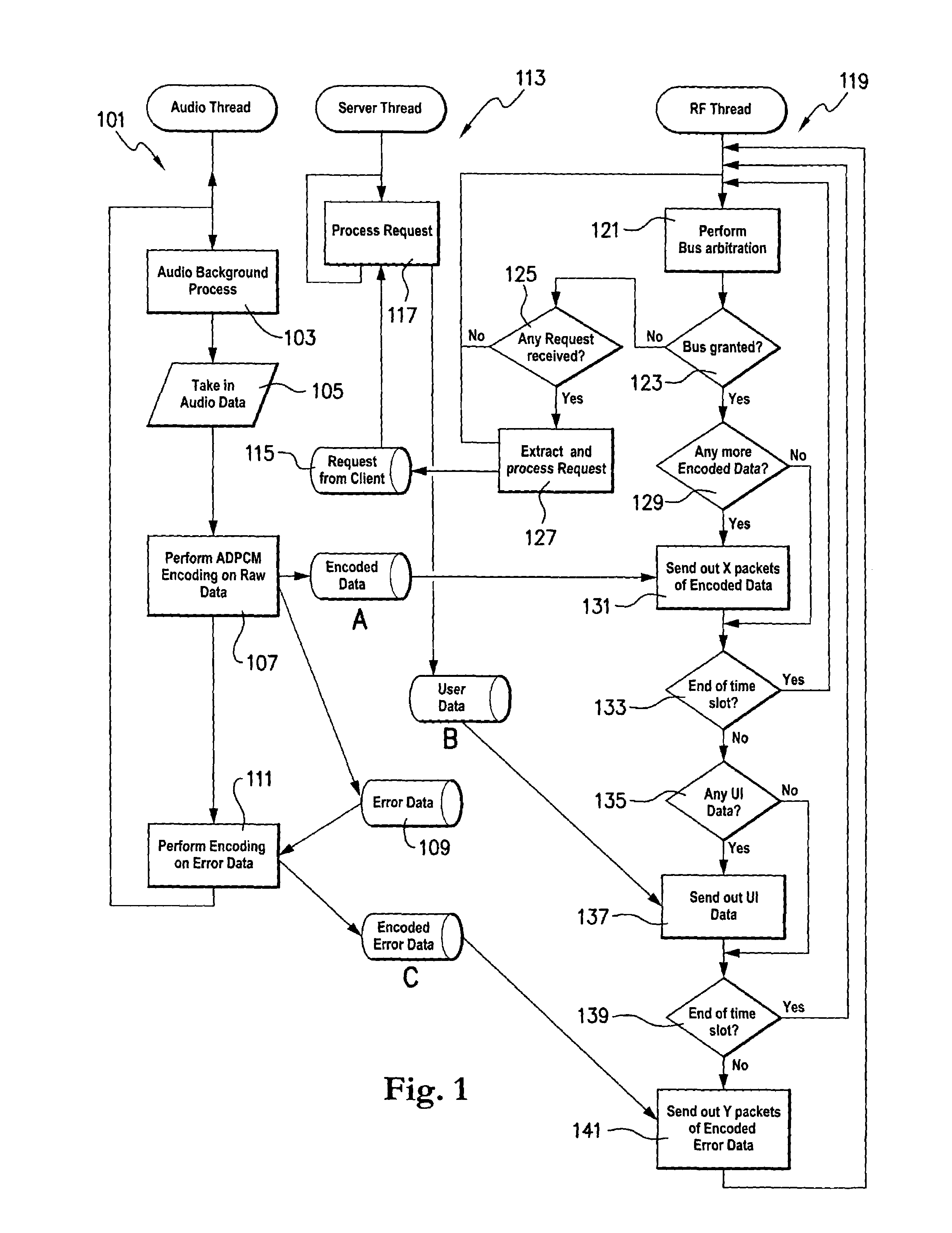
[0112]In the described embodiment, we consider a host station in the form of a server station and a plurality of client stations in the form of wireless client terminals. The server station is arranged to send encoded audio data, user data and encoded error data to the client terminals by RF and to receive requests from client terminals by RF. The client terminals are arranged to receive encoded audio data, user data and encoded error data from the server station by RF and to send client requests by RF to the server station.

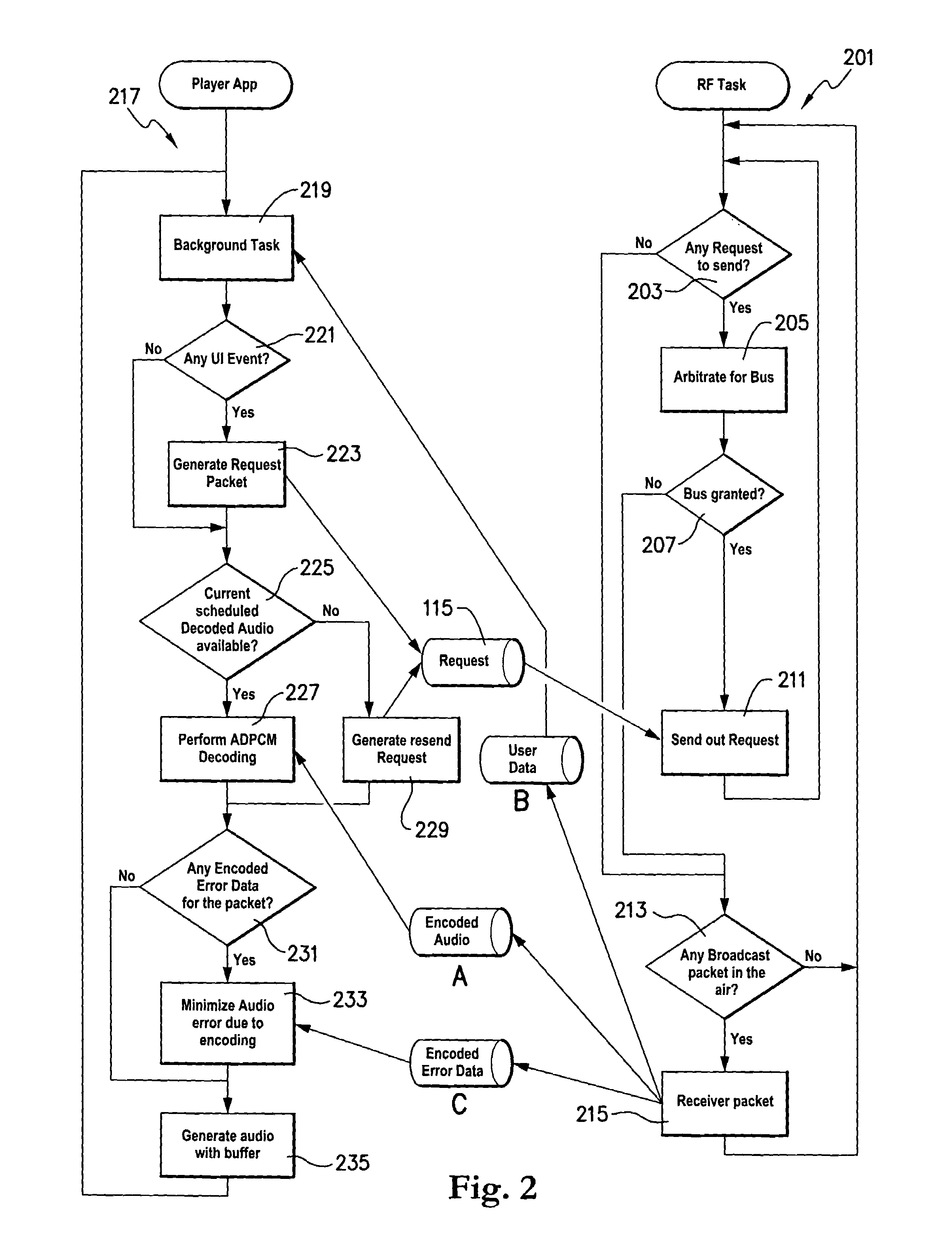
[0113]FIG. 1 is a flow chart showing operation at the server station. FIG. 2 is a flow chart showing operation at a given client terminal.

[0114]The flow chart of FIG. 1 is divided into three threads, showing the different aspects of operation. The first thread 101 is the audio thread. This part of the flow chart shows the processes performed by the server on the audio data. The second thread 113 is the server thread. This part of the flow chart shows the server o...


PUM


Abstract

There is provided a method and apparatus for sending an encoded signal between a host station and a client station in which the host station encodes data, encodes the error data resulting from that encoding process and generates user data. Thus, the host station generates three types of data and it accords different priorities to those three data types. The first type of data, the encoded original data is accorded the highest priority and is guaranteed delivery to a client station. Thus, a minimum signal quality is guaranteed at the client end. The second type of data, user data, is accorded a lower priority and will be delivered to the client station if there is available bandwidth once the encoded original data has been successfully delivered. The third type of data, encoded error data is accorded the lowest priority and is only delivered to the client station if there is available bandwidth once the encoded original data and the user data have been delivered. A minimum signal quality is ensured with enhancement allowed if possible. The receiving client station(s) may or may not be capable of decoding the error data and the quality at a particular client station will depend on whether it does so or not.

Description

FIELD OF THE INVENTION[0001]The invention relates to the field of encoded signal transmission. In particular, the invention relates to a method and apparatus for sending an encoded audio signal between a host station and a client station.BACKGROUND OF THE INVENTION[0002]Encoding data is a well known process to make more efficient use of a given bandwidth. An input signal (analogue or digital) is coded as a digital signal that occupies less bandwidth than the original signal. An encoder at the transmitting end encodes the original signal, the encoded signal is then sent across the channel and a decoder at the receiving end receives the encoded signal, decodes it and reconstructs the original signal.[0003]The quality of the reconstructed signal will depend on a number of factors including the complexity of the encoding and decoding system and the available bandwidth for transmission of the encoded signal. For audio signals, a user may well observe audio breakages especially when he is...

Claims


Application Information

Patent Timeline
Patent Type & Authority Patents(United States)
IPC IPC(8): H04L12/56
CPCH04L1/0041H04L1/08H04L1/1809H04L2001/0094
Inventor LEOW, SIEW KIATLIM, SONG GEECHEU, ENG YEOW
Owner CREATIVE TECH CORP
Why Eureka
Try Eureka