Intrabody navigation system for medical applications

a technology for medical applications and navigation systems, applied in the field of electromagnetic tracking devices, can solve the problems of reducing the accuracy of position and orientation measurements, unable to fit a receiver of sufficient sensitivity inside a medical probe, and fatally non-representative measurements at a single point, so as to achieve the effect of suppressing electromagnetic field distortion

Inactive Publication Date: 2009-06-30
COVIDIEN LP
View PDF20 Cites 75 Cited by
  • Summary
  • Abstract
  • Description
  • Claims
  • Application Information

AI Technical Summary

Benefits of technology

[0027]According to the present invention there is provided an imaging device, including: (a) an electrically conducting surface; (b) a magnetically permeable compensator; and (c) a mechanism for securing the compensator relative to the surface so as to substantially suppress a distortion of an external electromagnetic field caused by the surface.
[0041]With respect to intrabody navigation, the scope of the present invention includes the simultaneous acquisition and display of an image of the patient and superposition on that display of a representation of a probe inside the patient, with the representation positioned and oriented with respect to the image in the same way as the probe is positioned and oriented with respect to the patient. This is accomplished by positioning and orienting the imaging device with respect to the frame of reference of the transmitter, in one of two ways. Either the transmitter antennas are attached rigidly to the imaging device, or a second receiver is attached rigidly to the imaging device and the position and orientation of the imaging device with respect to the transmitter are determined in the same way as the position and orientation of the probe with respect to the transmitter are determined. This eliminates the need for fiducial points and fiducial markers. The scope of the present invention includes both 2D and 3D images, and includes imaging modalities such as CT, MRI ultrasound and fluoroscopy. Medical applications to which the present invention is particularly suited include transesophageal echocardiography, intravascular ultrasound and intracardial ultrasound. In the context of intrabody navigation, the term “image” as used herein refers to an image of the interior of the patient's body, and not to an image of the patient's exterior.
[0042]Under certain circumstances, the present invention facilitates intrabody navigation even if the image is acquired before the probe is navigated through the patient's body with reference to the image. A third receiver is attached rigidly to the limb of the patient to which the medical procedure is to be applied. During image acquisition, the position and orientation of the third receiver with respect to the imaging device is determined as described above. This determines the position and orientation of the limb with respect to the image. Subsequently, while the probe is being moved through the limb, the position and orientation of the probe with respect to the limb is determined using the second method described above to position and orient the probe with respect to the imaging device during simultaneous imaging and navigation. Given the position and orientation of the probe with respect to the limb and the orientation and position of the limb with respect to the image, it is trivial to infer the position and orientation of the probe with respect to the image.
[0043]Many imaging devices used in conjunction with the present invention include electrically conducting surfaces. One important example of such an imaging device is a fluoroscope, whose image intensifier has an electrically conducting front face. According to the present invention, the imaging device is provided with a magnetically permeable compensator to suppress distortion of the electromagnetic field near the electrically conducting surface as a consequence of eddy currents induced in the electrically conducting surface by the electromagnetic waves transmitted by the transmitting antennas of the present invention.

Problems solved by technology

Such a receiver of sufficient sensitivity would not fit inside a medical probe.
This reduces the accuracy of the position and orientation measurements, because instead of sensing three independent magnetic field components at the same point in space, this receiver senses three independent magnetic field components at three different, albeit closely spaced, points in space.
The high mutual coupling of collinear coils wound on ferrite cores and measuring three independent field components at three different points in space would distort those measurements sufficiently to make those measurements fatally nonrepresentative of measurements at a single point.
Another drawback of the system of WO 96 / 05768 relates to the geometry of the transmitter antennas.
Because the strength of the field transmitted by one of these coils falls as the reciprocal cube of the distance from the coil, the receiver usually senses fields of very disparate strength, which further degrades the accuracy of the position and orientation measurements.
Frequency multiplexing, as taught in WO 96 / 05768, overcomes this problem, but introduces a new problem insofar as the transmitting coils are coupled by mutual inductance at non-zero transmission frequency, so that the transmitted field geometry is not the simple geometry associated with a single coil, but the more complex geometry associated with several coupled coils.
This complicates and slows down the calculation of the position and orientation of the receiver relative to the transmitter coils.
A further source of slowness in calculating the position and orientation of the receiver is the iterative nature of the calculation required for a spatially extended transmitter.

Method used


Image

  • Intrabody navigation system for medical applications
  • Intrabody navigation system for medical applications
  • Intrabody navigation system for medical applications

Examples


Embodiment Construction

[0068]The present invention is of a system and method for tracking the position and orientation of an object relative to a fixed frame of reference. Specifically, the present invention can be used to track the motion of a medical probe such as a catheter or an endoscope within the body of a patient.

[0069]The principles and operation of remote tracking according to the present invention may be better understood with reference to the drawings and the accompanying description.

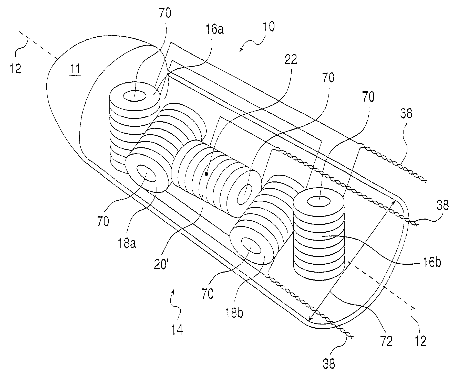
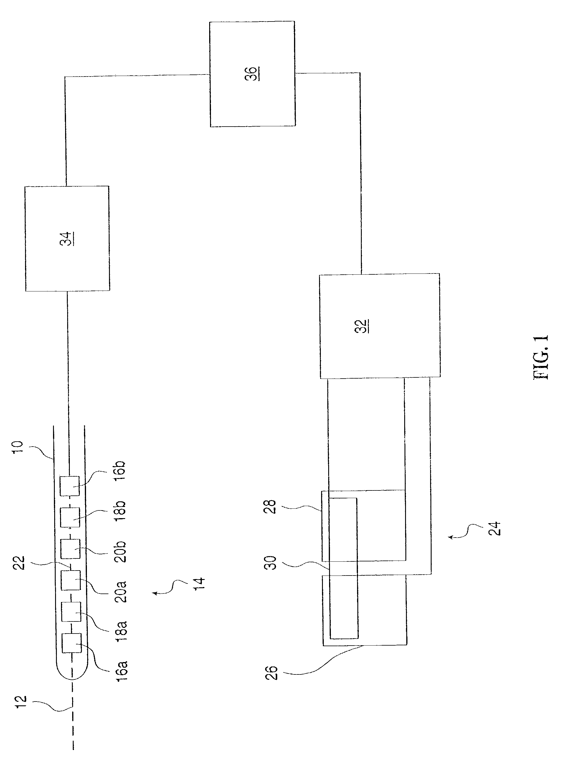
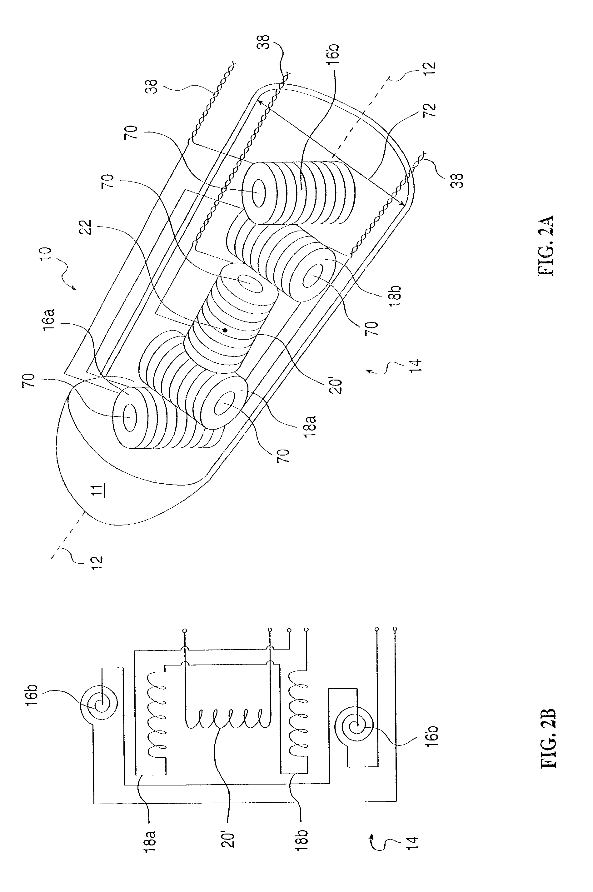
[0070]Referring now to the drawings, FIG. 1 illustrates, in general terms, a system of the present invention. Within a probe 10 is rigidly mounted a receiver 14. Receiver 14 includes three field component sensors 16, 18, and 20, each for sensing a different component of an electromagnetic field. Sensor 16 includes two sensor elements 16a and 16b. Sensor 18 includes two sensor elements 18a and 18b. Sensor 20 includes two sensor elements 20a and 20b. Typically, the sensor elements are coils, and the sensed component...


PUM


Abstract

A system and method for tracking the position and orientation of a probe. Three at least partly overlapping planar antennas are used to transmit electromagnetic radiation simultaneously, with the radiation transmitted by each antenna having its own spectrum. A receiver inside the probe includes sensors of the three components of the transmitted field, with sensors for at least two of the three components being pairs of sensors, such as coils, on opposite sides of a common reference point. In one variant of the receiver, the coils are collinear and are wound about cores that are mounted in pairs of diametrically opposed apertures in the housing of the probe. Each member of a pair of coils that sense the same component of the transmitted field is connected to a different input of a differential amplifier. The position and orientation of the receiver relative to the antennas are determined noniteratively.

Description

[0001]This file is a Continuation of U.S. patent application Ser. No. 09 / 463,177 filed Jan. 21, 2000, now U.S. Pat. No. 6,593,884, which in National Phase of PCT / IL99 / 00371 filed Jul. 7, 1999 and claiming priority from Israel Patent Applications No. 125626 and Israel Patent Application No. 126814, both now abandoned.FIELD AND BACKGROUND OF THE INVENTION[0002]The present invention relates to electromagnetic tracking devices and, more particularly, to a system and method for tracking a medical probe such as a catheter as the probe is moved through the body of a patient.[0003]It is known to track the position and orientation of a moving object with respect to a fixed frame of reference, by equipping the moving object with a transmitter that transmits electromagnetic radiation, placing a receiver in a known and fixed position in the fixed frame of reference, and inferring the continuously changing position and orientation of the object from signals transmitted by the transmitter and rec...

Claims


Application Information

Patent Timeline
Patent Type & Authority Patents(United States)
IPC IPC(8): A61B5/05G01S3/02G01S5/04A61B1/00A61BA61B5/00A61B5/055A61B5/06A61B5/296A61B6/03A61B6/12A61B8/00A61B8/08A61B8/12A61B19/00A61M25/00A61M25/095G01B7/00G01R33/02G01R33/34G01R33/36
CPCA61B5/06A61B19/5244A61B5/055A61B6/032A61B8/08A61B2019/5251A61B2019/5272A61B8/4245A61B2034/2072A61B34/20A61B2034/2051A61B5/062
Inventor GILBOA, PINHASBLECHER, DANNY
Owner COVIDIEN LP
Why Eureka
Try Eureka