Renewably buoyant, self-protective floating habitat

a floating habitat, self-protective technology, applied in the field of floating habitats, can solve the problems of increasing land mass and corresponding decrease in water volume, reducing aesthetic appearance, killing fish and other organisms, etc., and achieve the effect of improving the appearance and optimizing the nesting habita

Inactive Publication Date: 2009-07-07
FOUNTAINHEAD
View PDF30 Cites 12 Cited by
  • Summary
  • Abstract
  • Description
  • Claims
  • Application Information

AI Technical Summary

Benefits of technology

[0020]The present invention involves a floating habitat that is designed to be renewably buoyant and self-sustaining. The floating habitat comprises buoyant growth medium and optionally includes one or more inflatable bladders. The growth medium can be made of natural or synthetic material and can include plant growth enhancers. The inflatable bladders can be transparent or opaque and rigid or flexible. Gas-producing microorganisms can be added to the growth medium to provide additional buoyancy.
[0023]The floating habitat described above can also be specialized for waterfowl nesting. In this embodiment, the floating habitat includes one or more waterfowl nesting structures and, optionally, a predator control device. Live vegetation is selected based on the nesting preferences of a particular species of waterfowl, and the construction material and screen size of the top and bottom mesh are selected to optimize the nesting habitat. The present invention also includes a method of combining any number of the floating habitats described herein to provide safe habitat for juvenile waterfowl, to encourage colony nesting, or to allow for a variety of waterfowl or shore bird species to enjoy suitable habitat on the same floating habitat system. In an alternative embodiment, one or more waterfowl nesting structures are combined with an impermeable closed bag.
[0024]The present invention also includes a number of different embodiments of a waterfowl nesting structure that is made our of scrap pieces of polyester mesh material, expandable foam, and optionally, scrap pieces of closed cell foam. The sides of the habitat can be comprised of smooth, rigid plastic sheeting to prevent swimming animals from boarding the habitat. Camouflage material can be added to provide protection for a nesting area and / or nesting cavity. Jute or a similar natural-looking material can be added to the top of the structure to improve its appearance. The bottom of the habitat can be either penetrable or non-penetrable by plant roots, as desired.

Problems solved by technology

In bodies of water such as ponds and lakes, algae growth and the natural process of eutrophication can lead to an increase in land mass and corresponding decrease in water volume, the killing of fish and other organisms, and the diminishment of aesthetic appearance.
It is well known that nitrogen and phosphorous are primary food sources for various undesirable algae species, and ammonia and heavy metals are toxic to humans, fish and other organisms.

Method used


Image

  • Renewably buoyant, self-protective floating habitat
  • Renewably buoyant, self-protective floating habitat
  • Renewably buoyant, self-protective floating habitat

Examples


first embodiment

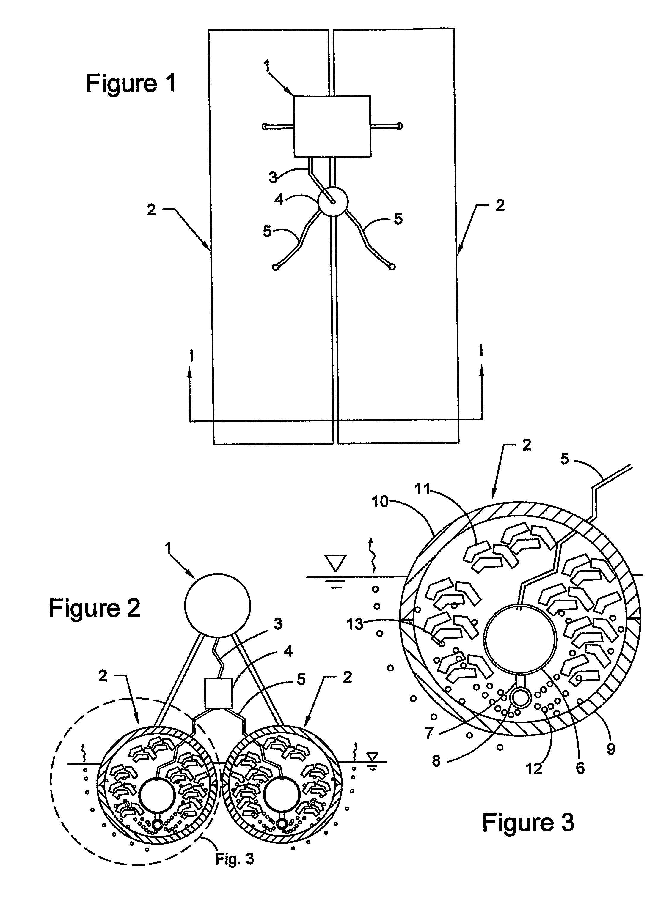
[0052]The floating habitat of the present invention is equipped with components that supply pressurized air to the submerged portions of the structure in order to increase the overall buoyancy of the structure. There are several alternative configurations for the air supply system. the self-pressurized floating habitat system is shown in top view in FIG. 1. A compressed air source 1 is shown mounted on top of flotation units 2. Although the drawing depicts the use of two flotation units 2, any number may be used, depending on the selected size of each flotation unit 2 and the required buoyancy and overall size of the floating habitat. Compressed air is produced by the compressed air source 1, pumped through the main supply hose 3 to the distribution valve 4, and then to the individual supply hoses 5.

[0053]FIG. 2 is a section view taken at section I-I of FIG. 1, and it shows the compressed air source 1, the flotation units 2, the main supply hose 3, the distribution valve 4, and an i...

second embodiment

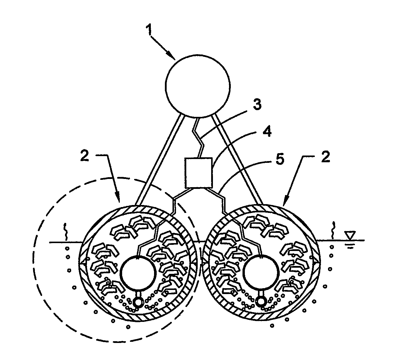
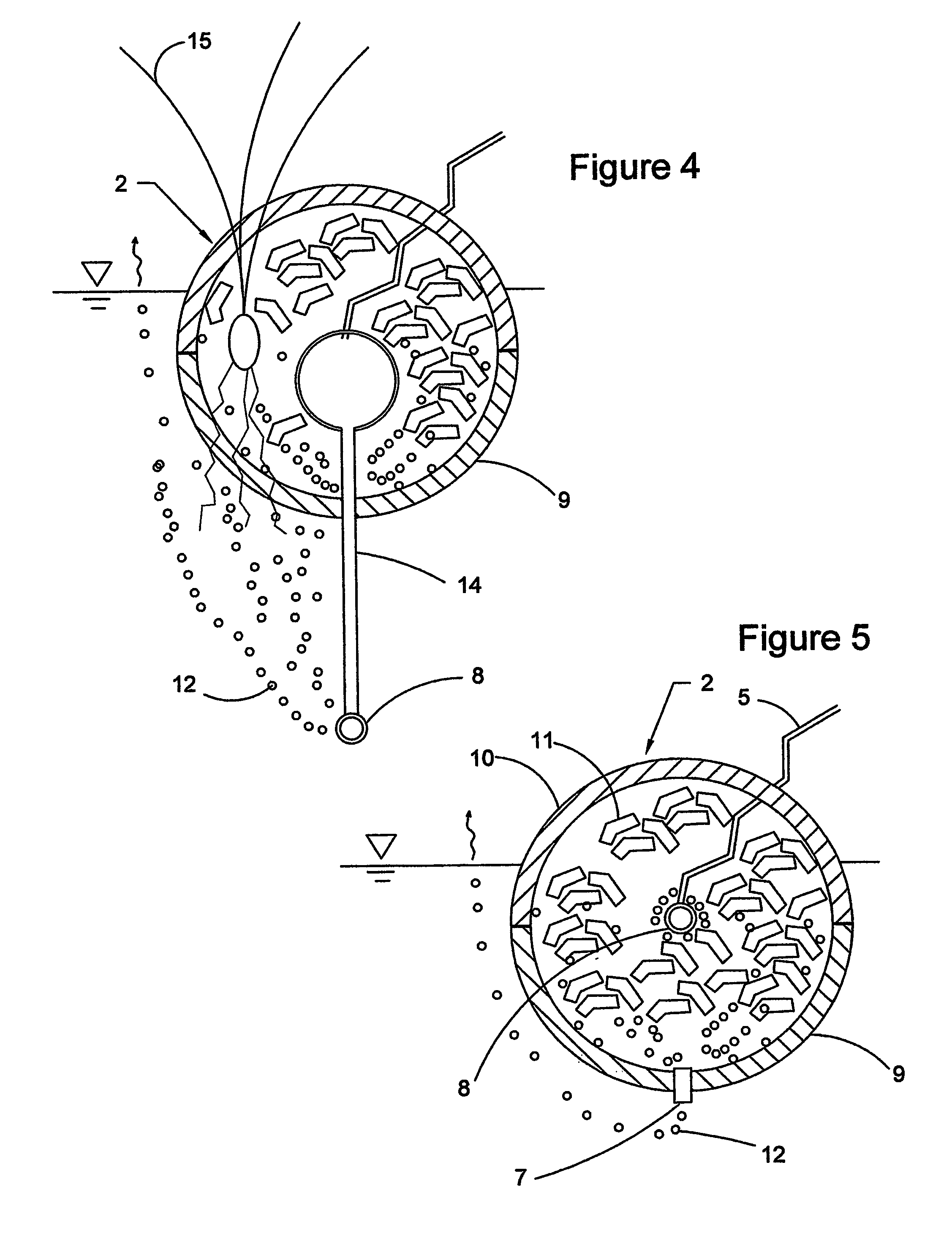
[0059]a flotation unit 2 is shown in cross section in FIG. 4. In this embodiment, an extension tube 14 is used to position the diffusing manifold 8 beneath the flotation unit 2. Excess air is released through the diffusing manifold 8 into the water body in which the structure is floating. The released air bubbles 12 rise through the water body, where a first portion of the bubbles 12 dissolves into the water, a second portion adheres to the roots of aquatic plants 15 that extend through the bottom mesh 9, and the remainder of the bubbles is dispersed as described for FIG. 3. An advantage of this “extended manifold” embodiment is that it provides a means for increasing the dissolved air concentration in the water body, especially in the vicinity of the structure.

third embodiment

[0060]a flotation unit 2 is shown in cross section in FIG. 5. In this embodiment, bottom cover 9 and top cover 10 are made of impermeable materials so that they cannot be penetrated by plants, air bubbles, or water. Air enters the flotation unit 2 through an individual supply hose 5 and is released through a diffusing manifold 8, causing the internal pressure of the flotation unit 2 to increase. When the pressure increases to the opening pressure of the relief valve 7, excess air is released through the relief valve 7 to the water body in the form of air bubbles 12. This embodiment may be advantageous for applications where plant growth on the structure is not desired.

[0061]Three alternative embodiments of the compressed air source 1 are shown in FIGS. 6, 7, 8 and 9. The first preferred embodiment of the compressed air source 1 shown in FIG. 6 is a wind-powered compressor 16. A second preferred embodiment of the compressed air source 1 is the photoelectric-compressor system 17 shown...


PUM


Abstract

A floating habitat designed to be renewably buoyant, self-sustaining and optionally specialized for waterfowl nesting. The first embodiment comprises one or more flotation units and a source of compressed air that is connected to the flotation units. Each flotation unit comprises an individual supply hose, an inflatable bladder, a relief valve, a diffusing manifold, bottom mesh, top mesh, and buoyant growth medium. An alternative embodiment comprises a self compensating buoyancy system. In the waterfowl nesting embodiment, the floating habitat includes one or more waterfowl nesting structures and construction material selected to optimize the nesting habitat. The floating habitat can be comprised of scrap pieces or layers of polyester mesh material. The Boating habitats can be combined to provide safe habitat for juvenile waterfowl, encourage colony nesting, or allow a variety of waterfowl or shore bird species to enjoy suitable habitat on the same floating habitat.

Description

CROSS-REFERENCE TO RELATED APPLICATION[0001]This application claims priority back to U.S. Patent Application No. 60 / 609,187 filed on Sep. 10, 2004 and U.S. Patent Application No. 60 / 529,060 filed on Dec. 12, 2003. The contents of these applications are hereby incorporated by reference into the present disclosure.BACKGROUND OF THE INVENTION[0002]1. Field of the Invention[0003]The present invention relates to a floating habitat that has a dynamic ability to generate its own buoyancy, through the use of external power or by replicating the biotic activity that occurs on wild floating islands. The present invention encompasses a number of different embodiments directed toward providing waterfowl nesting habitat.[0004]2. Description of the Related Art[0005]Naturally occurring floating islands are a relatively unique phenomenon, but they do exist in several places in the world, including Australia, Bangladesh, Fiji, Germany, Hungary, India, Italy, Japan, Mexico, Poland, Turkey, Uganda and...

Claims


Application Information

Patent Timeline
Patent Type & Authority Patents(United States)
IPC IPC(8): A01G31/00A01G9/00A01KA01K31/14A01K61/00A01K67/033
CPCA01G9/00A01K31/14A01K67/033A01K61/007A01K61/006A01K61/60A01K61/70Y02P60/60Y02A40/81
Inventor KANIA, BRUCE G.STEWART, FRANK M.SMITH, RUSSELL F.COLEMAN, THOMAS N.CUNNINGHAM, ALFRED
Owner FOUNTAINHEAD
Why Eureka
Try Eureka