Bicycle rear wheel suspension chassis

Inactive Publication Date: 2009-07-07
DUNLAP CHARLES E
View PDF25 Cites 31 Cited by
  • Summary
  • Abstract
  • Description
  • Claims
  • Application Information

AI Technical Summary

Benefits of technology

[0019](g) to provide a moving instant center that moves forward as the rear suspension is compressed. The forward movement of said moving instant center results in a higher rear suspension chassis natural frequency at the start of the suspension compression. As the suspension is compressed said rear suspension chassis natural frequency decreases. The initial higher natural frequency gives the bicycle rider better control over high frequency/small amplitude impacts, while the lower natural frequency gives the bicycle rider better control over the lower frequency/large amplitude bumps. The advantage is a suspension chassis that responds appropriately to varying impacts giving the bicycle rider maximum control.
[0020]In accordance with the present invention, the unique geometric arrangement lowers the center of gravity of the bicycle compared to prior art designs by placing the suspension chassis members in a lower position than prior art while still reacting to help travel over trail obstacles. Lower center of gravity reduces the swing inertia of the bicycle while providing greater stability in handling and cornering.
[0021]While reacting to travel over objects in the trail, the unique suspension chassis also protects the bicycle rear wheel from taller trail objects that can make it difficult for the rider to travel over. The unique linkage de

Problems solved by technology

Skid plates have been used on bicycles in prior art but these applications failed to use the skid plate as a means to activate t

Method used


Image

  • Bicycle rear wheel suspension chassis
  • Bicycle rear wheel suspension chassis
  • Bicycle rear wheel suspension chassis

Examples


Embodiment Construction

—PREFERRED EMBODIMENT—FIG. 101, 102, 103, 104, 105

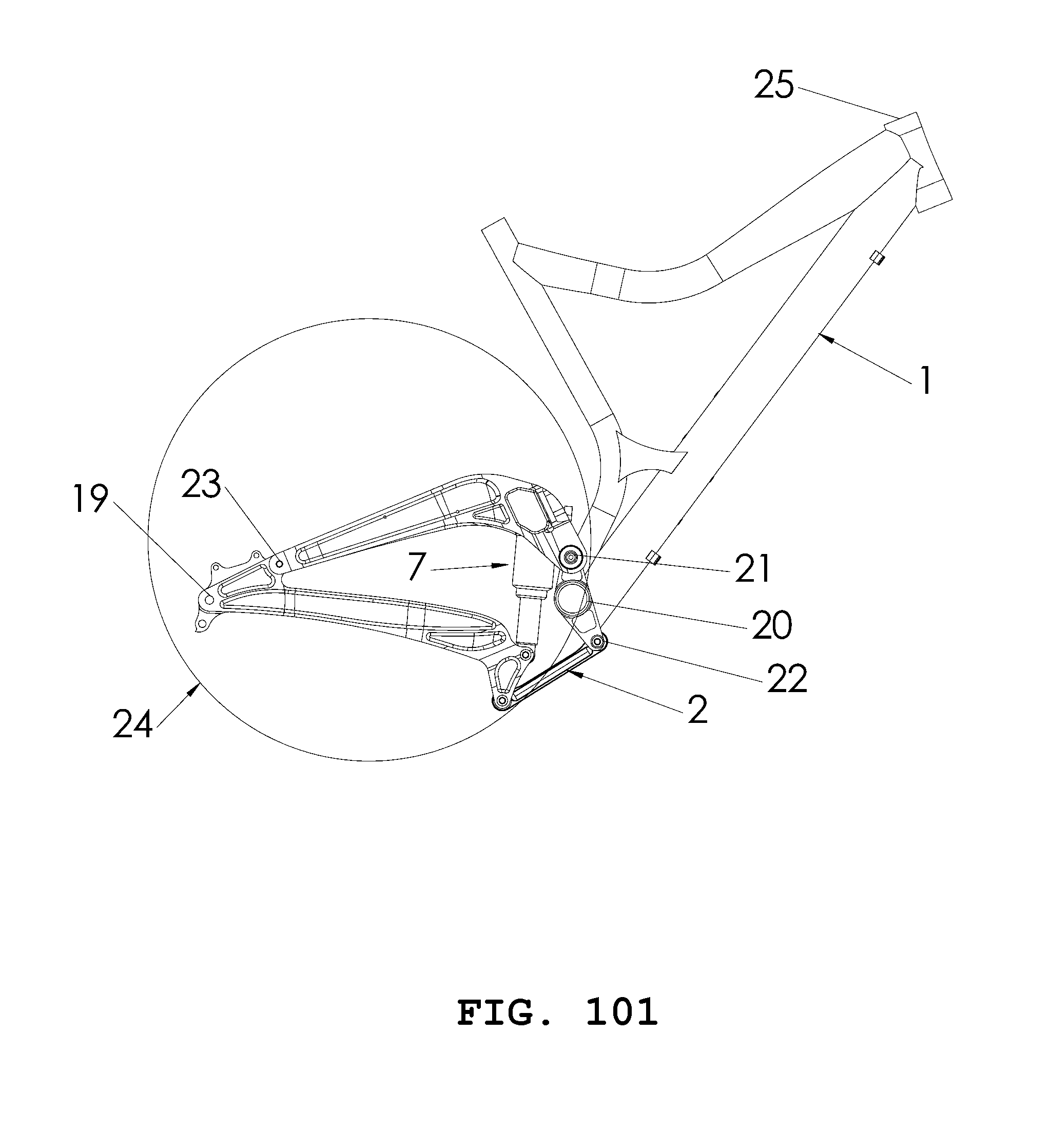
[0066]The system according to a preferred embodiment of the present invention in FIGS. 101, 102, 103, 104, and 105 comprises of a Bicycle Rear Wheel Suspension Chassis.

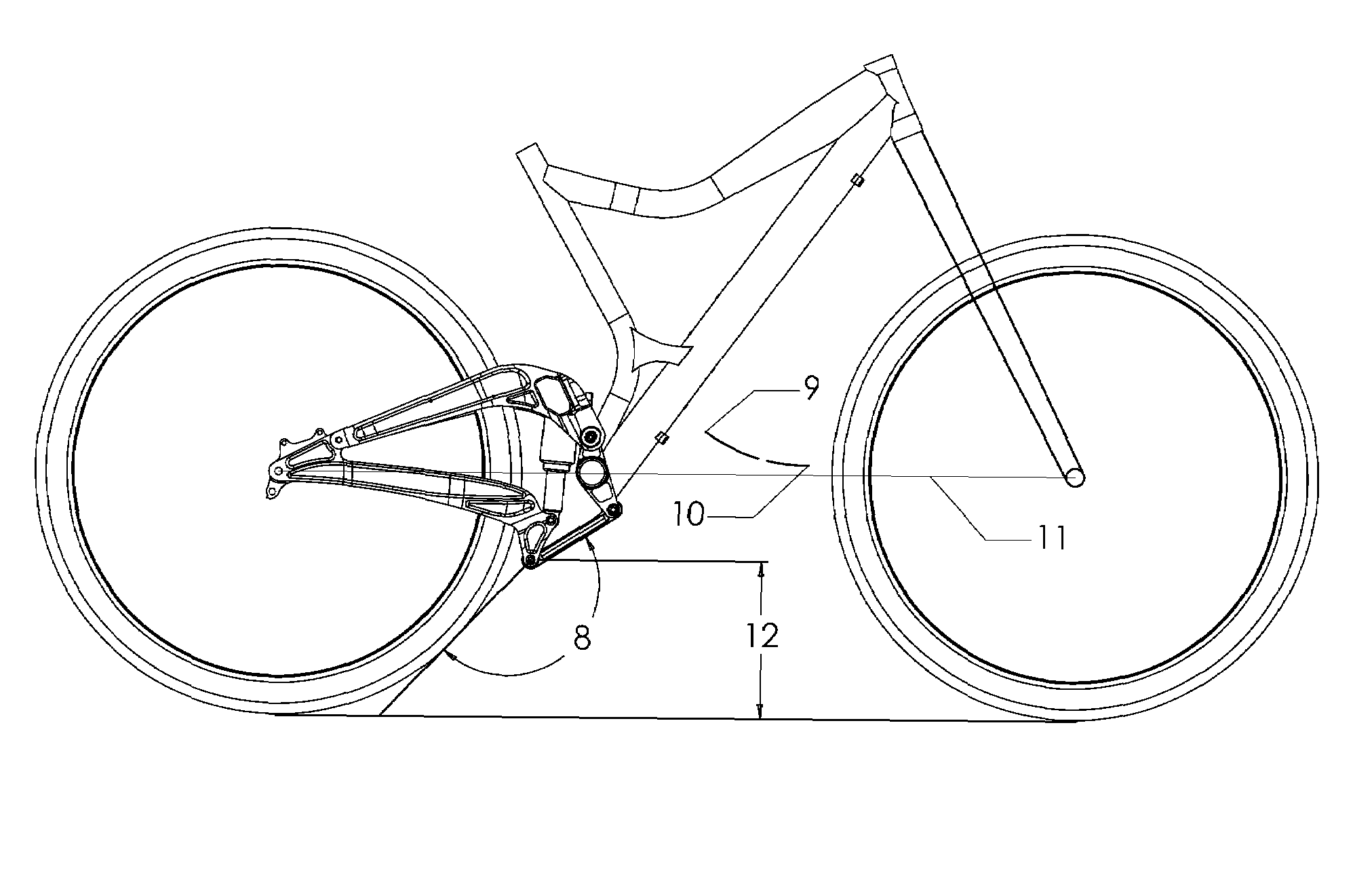
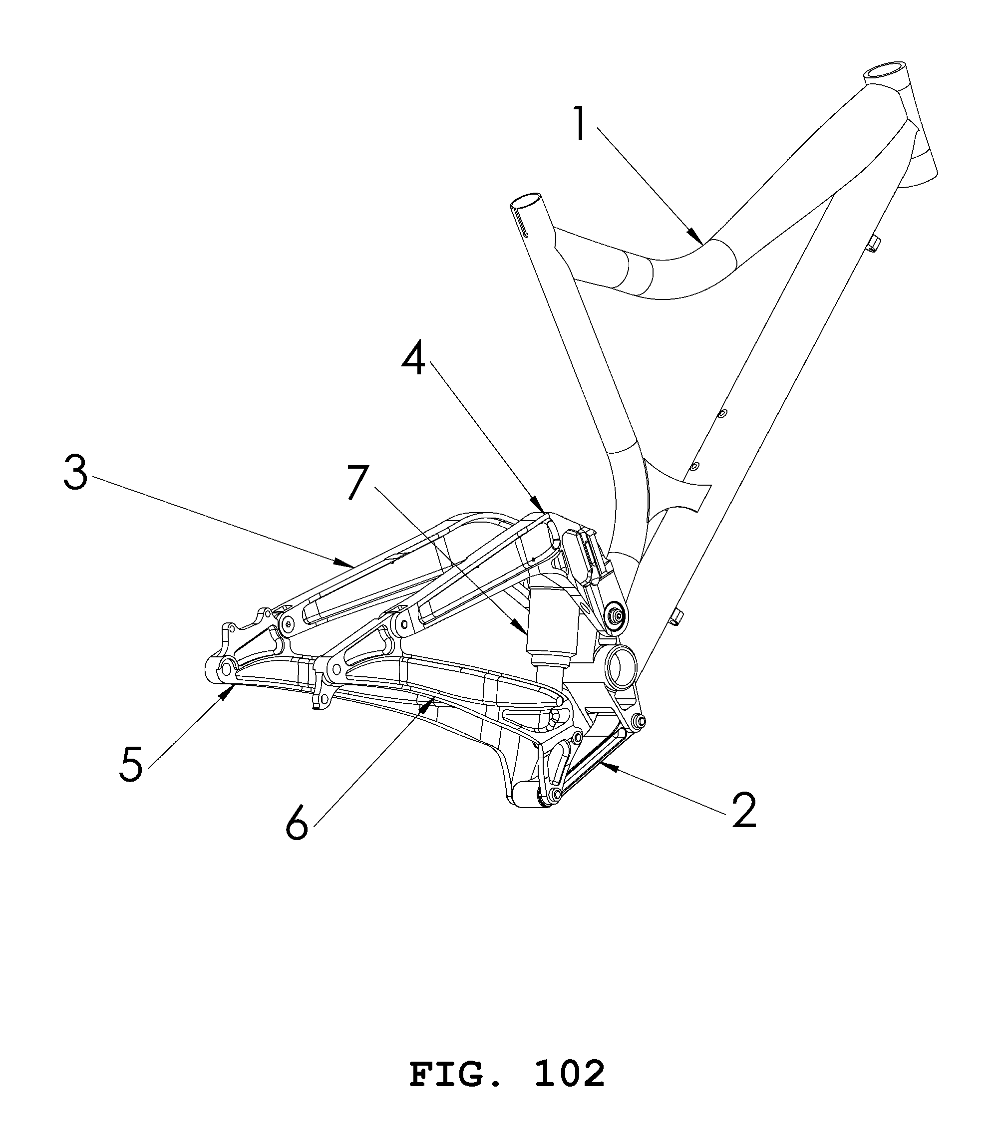
[0067]FIG. 101 shows a side view of the preferred embodiment of the present invention. The Front Triangle Frame 1 is a welded structure or similar. The Steering Housing 25 pivotally attaches to handlebars, fork and front wheel. The Crank Shaft Housing 20 pivotally attaches to a crank system for pedaling. A rear wheel pivotally attaches to the Rear Axle Location 19. The Link 2 pivotally attaches to the Lower Pivot 2. The Rear Pivot 23 is above and forward from said Rear Axle Location 19. Said Lower Pivot 22 is approximately 50 mm below the geometric center of said Crank Shaft Housing 20. The Upper Pivot 21 is above said Crank Shaft Housing 20. The Rear Shock Absorber 7 is attached to the Swingarm Chassis 24, providing means for suspension spring rate and damping.

[0068]F...


PUM


Abstract

A Bicycle Rear Wheel Suspension Chassis for a Bicycle. Improved performance, low center of gravity, and ground clearance result from a Front Triangle Frame 1 with Steering Housing 25 and Crank Shaft Housing 20, a Link 2 with forward most end pivotally attached to Lower Pivot 22, a Swingarm Chassis 24 pivotally attached to rearward most end of said Link 2, and a rear wheel pivotally attached at Rear Axle Location 19 to said Swingarm Chassis 24. The Shock Absorber 7 attached to said Swingarm Chassis 24 provides means for suspension spring rate and damping for isolating a bicycle rider from trail impacts with the rear wheel. Performance and handling advantages result from a low center of gravity system, a Link 2 at the Lower Pivot 22 that provides better control by reacting to travel over trail objects, and a moving instant center that reacts optimally to impacts of varying magnitude and frequency.

Description

CROSS REFERENCE TO RELATED APPLICATIONS[0001]None.FEDERALLY SPONSORED RESEARCH[0002]None.SEQUENCE LISTING[0003]None.BACKGROUND OF THE INVENTION[0004]1. Field of Invention[0005]This invention relates to rear suspension bicycle frames, particularly off-road rear suspension bicycles used on terrain with varying conditions and surfaces, with loose and immovable objects to travel over.[0006]2. Prior Art[0007]Rear suspension has proven to be a benefit in comfort and performance bicycles. This benefit is especially realized with off-road bicycles. Rear bicycle suspension absorbs shock from road and / or trail surface variations. By absorbing impacts, tire traction is improved giving the rider improved control of the bicycle. Improved tire traction is a benefit in lateral, forward, and rearward directions. Cornering, turning, accelerating, climbing, and braking are improved.[0008]Typical rear bicycle suspension designs found in prior art are comprised of linkages, similar to those used in aut...

Claims


Application Information

Patent Timeline
IPC IPC(8): B62K25/28
CPCB62K25/30B62K25/286
Inventor DUNLAP, CHARLES EMET
Owner DUNLAP CHARLES E
Why Eureka
Try Eureka