Machine for mixing and extruding rubber-based and silicone-based plastic materials and method therefor

a technology of rubber-based and silicone-based plastic materials and machines, which is applied in the field of machines for mixing and extruding rubber-based and silicone-based plastic materials and the method therefor, which can solve the problems of high injury risk, bulky cylinder mixers, and expensive non-automatic machines

Active Publication Date: 2009-07-07
COLMEC
View PDF10 Cites 42 Cited by
  • Summary
  • Abstract
  • Description
  • Claims
  • Application Information

AI Technical Summary

Problems solved by technology

The cylinder mixer is a bulky, expensive and non-automatic machine, and exposes the operator to a high level of injury hazard.

Method used


Image

  • Machine for mixing and extruding rubber-based and silicone-based plastic materials and method therefor
  • Machine for mixing and extruding rubber-based and silicone-based plastic materials and method therefor
  • Machine for mixing and extruding rubber-based and silicone-based plastic materials and method therefor

Examples


Embodiment Construction

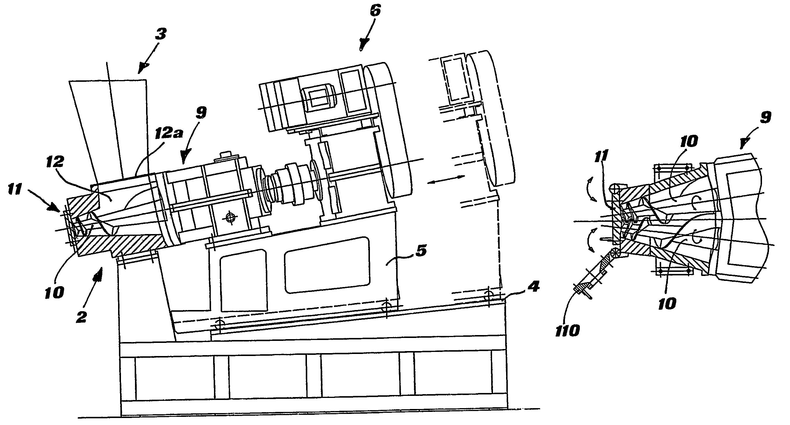
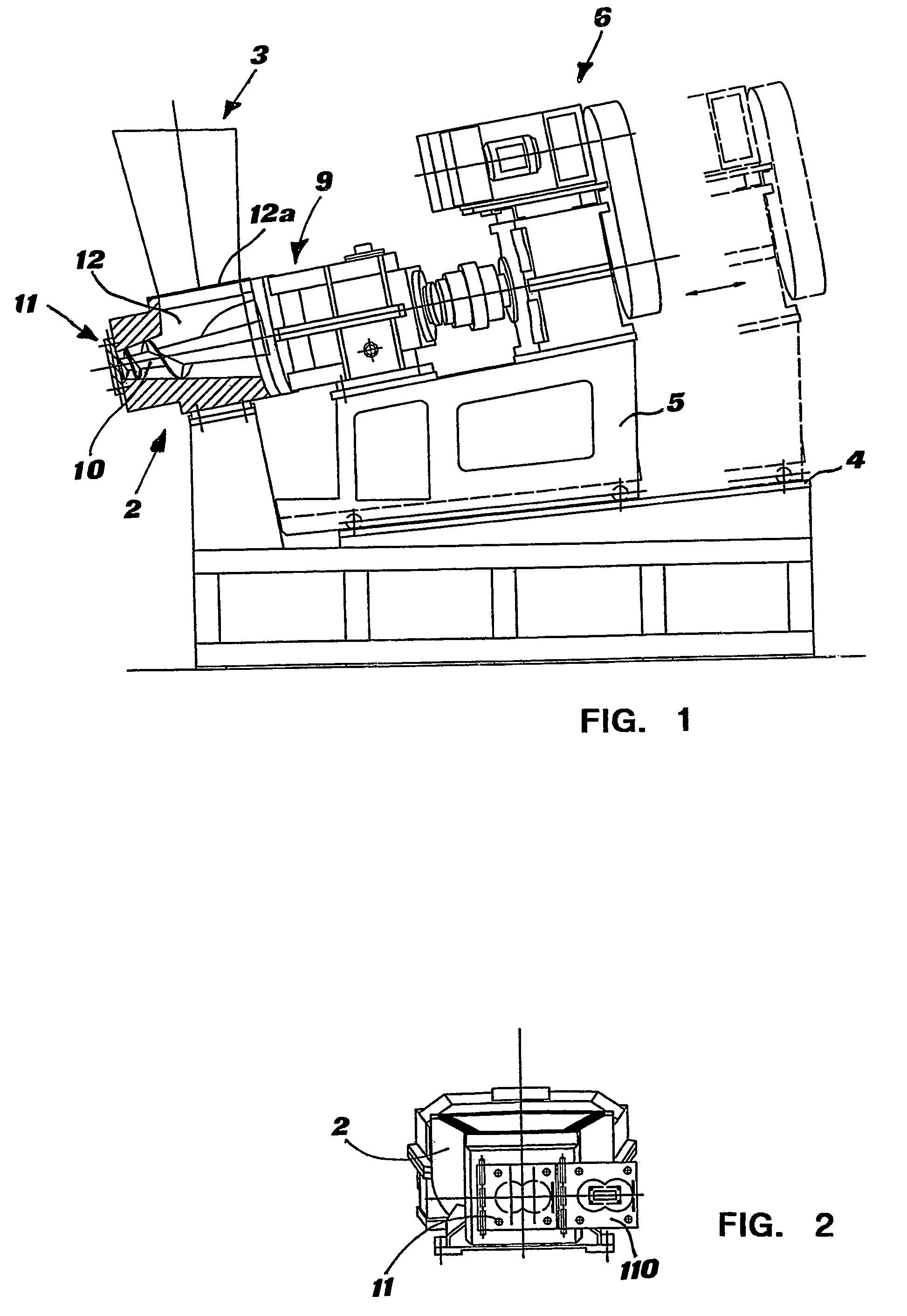
[0016]A mixer according to the invention mainly comprises a cone-shaped twin-screw extruder typically called dump extruder, as shown in FIG. 1, for example the model CTE (Conical Twin Extruder) by Colmec S.p.A.

[0017]The mixer comprises a fixed base from whose front end a post rises that supports a twin-screw body 2 provided with a feedbox 3. The upper surface of the fixed base is further provided with rails 4 onto which is capable of translating a sliding support 5 of a motor body 6.

[0018]Belonging to the motor body 6 are also a reduction unit 7, a joint 8 and a support box 9 of the extrusion screws, from which depart two conical screws 10 housed in a batching chamber of the twin-screw body 2.

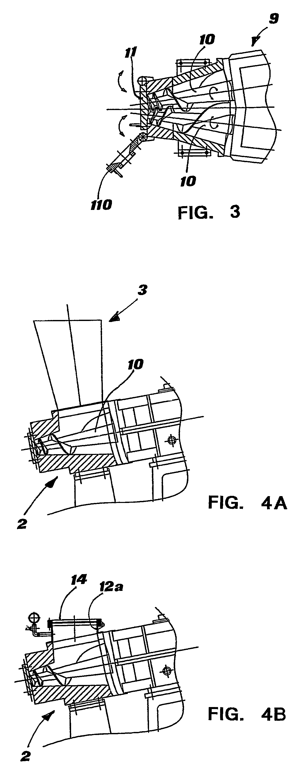
[0019]As can be observed in FIG. 3, the two conical screws 10 are intermeshing and converge towards the outlet of the twin-screw body 2. They are driven to rotate by the motor body 6 in counterrotation mode.

[0020]Furthermore, the batching chamber 12 opens towards the feedbox 3 through a mouthpi...


PUM

PropertyMeasurementUnit
pressureaaaaaaaaaa
shapeaaaaaaaaaa
total poweraaaaaaaaaa

Abstract

A machine for the mixing and extrusion of rubber-based and silicone-based plastic materials and method thereof is disclosed, comprising a dump extruder with conical converging twin screws (10) arranged in a batching chamber (12) in which the outlet of the dump extruder is temporarily closed by a removable blind flange (11), the batching chamber also acting as a compounding chamber.

Description

FIELD OF THE INVENTION [0001]The present invention relates to a machine for the mixing and extrusion of rubber-based and silicone-based plastic materials and the method therefor.BACKGROUND OF THE INVENTION [0002]It is known that, in modern processes for the preparation of rubber compounds, a system is employed consisting of a closed mixer, commonly called “Banbury mixer”, paired with a twin-screw extruder called “Dump Extruder” (FIG. 5). The system provides that the raw material, typically rubber, or a silicone-based polymer, is mixed with fillers and various additives in a closed Banbury-type (from the name of its inventor) mixer, from which, at regular intervals, an evenly-mixed compound comes out, called “batch”, which falls into the feedbox of the dump extruder lying below.[0003]In other words, during operation, the closed mixer delivers at regular intervals batches of compounded material to the dump extruder, which has instead the function of transforming the compound batch so ...

Claims


Application Information

Patent Timeline
Patent Type & Authority Patents(United States)
IPC IPC(8): B29B7/20B01F7/08B29C47/40B29B7/74B29C48/525
CPCB01F7/082B29B7/20B29B7/7495B29C47/402B29C47/6012B29C47/38B29C47/0021B29K2083/00B29K2021/00B29B7/26B29C48/08B29C48/395B29C48/402B29B7/183B29B7/52B29B7/802B29C48/525B29B7/582B29B7/484B29B7/60B01F27/722
Inventor COLOMBO, UBALDO
Owner COLMEC
Why Eureka
Try Eureka