Turbine airfoil with multiple near wall compartment cooling

a turbine airfoil and near wall cooling technology, which is applied in the direction of liquid fuel engines, machines/engines, mechanical equipment, etc., can solve the problems of blade hot spots along the span-wise, and difficult to achieve the span-wise and chord-wise cooling flow control due to airfoil external hot gas temperature and pressure variation,

Inactive Publication Date: 2009-07-07
FLORIDA TURBINE TECH
View PDF21 Cites 77 Cited by
  • Summary
  • Abstract
  • Description
  • Claims
  • Application Information

AI Technical Summary

Problems solved by technology

As a result of this cooling construction approach, span-wise and chord-wise cooling flow control due to airfoil external hot gas temperature and pressure variation is difficult to achieve.
In addition, single radial channel flow is not the best method of utilizing cooling air, resulting in a low convective cooling effectiveness.
One problem with this design is that the blade may have hot spots along the span-wise direction.
This is a long flow path for the cooling air, which results in lower efficiency because the cooling air heats up before reaching the middle and trailing edge portions of the airfoil.

Method used


Image

  • Turbine airfoil with multiple near wall compartment cooling
  • Turbine airfoil with multiple near wall compartment cooling
  • Turbine airfoil with multiple near wall compartment cooling

Examples


Embodiment Construction

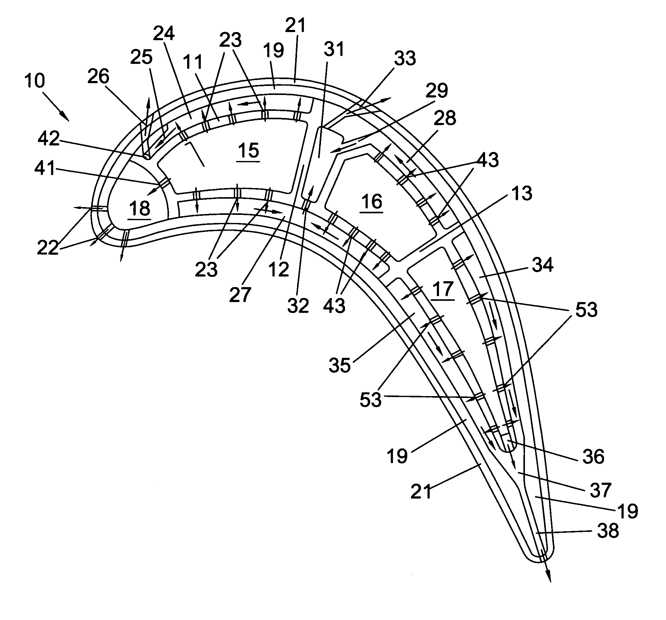
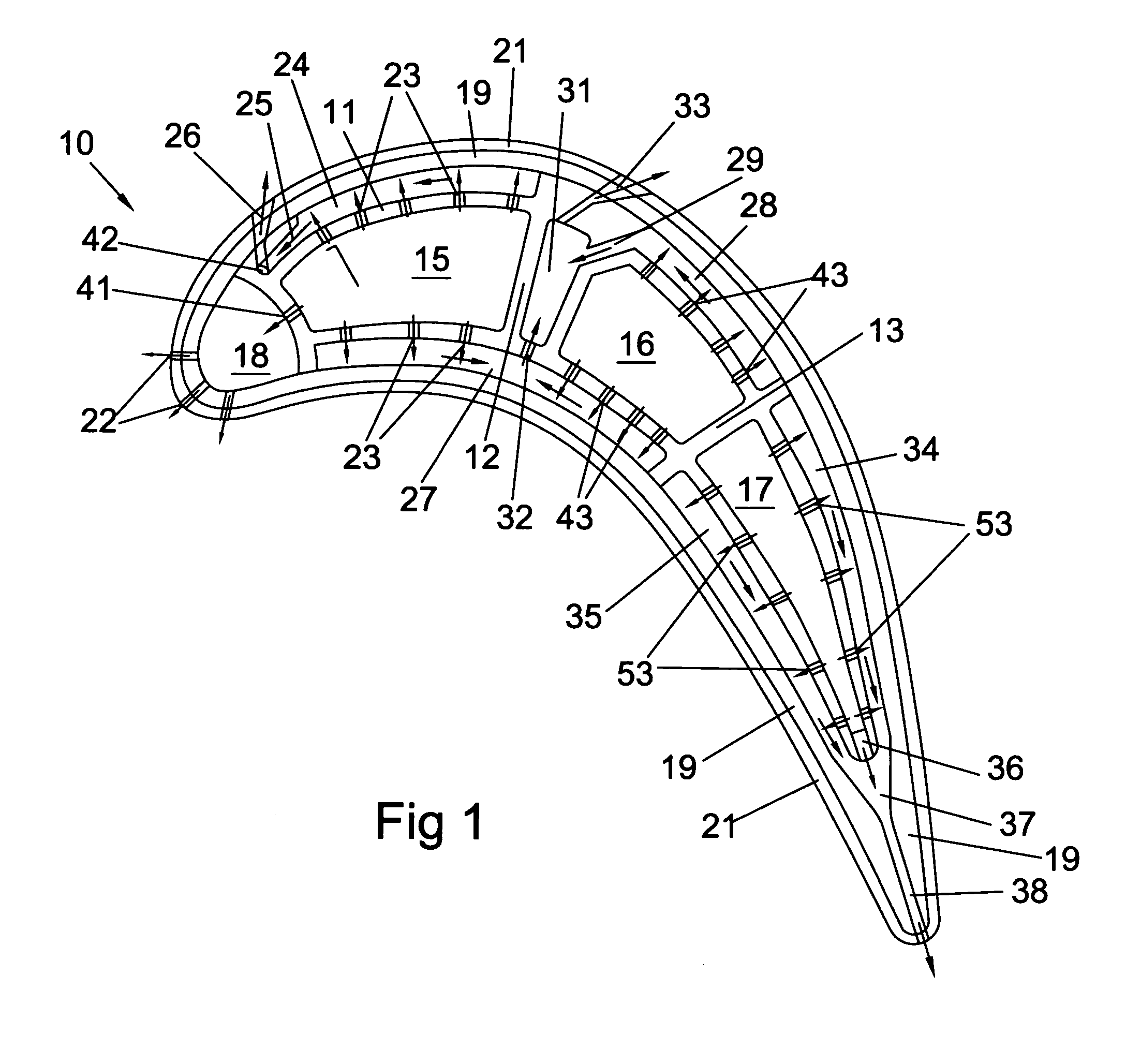
[0013]The present invention is a turbine airfoil such as a rotor blade with a cooling circuit that provides convective cooling to the airfoil main body, and impingement cooling and film cooling to the outer wall of the airfoil in order to maximize the cooling while minimizing the amount of cooling air used. FIG. 1 shows the blade 10 of the present invention in a cross section view. The blade 10 includes a blade main body 11 having the general shape of the airfoil with a leading edge and a trailing edge, and a pressure side and a suction side. The blade main body includes walls of such thickness to provide sufficient structural strength to support the airfoil assembly 10. The blade main body 11 includes a rib 12 that separates a first or forward cooling air supply channel 15 from a spent air collector cavity 31. Another rib separates the spent air collector cavity 31 from a second or mid-chord cooling air supply channel 16. A third rib 13 separates the second or mid-chord channel 16 ...


PUM


Abstract

The present invention is a turbine airfoil such as a rotor blade with a cooling circuit that provides convective cooling to the airfoil main body, and impingement cooling and film cooling to the outer wall of the airfoil in order to maximize the cooling while minimizing the amount of cooling air used. The blade main body includes walls of such thickness to provide sufficient structural strength to support the airfoil assembly. The blade main body includes a rib that separates a first or forward cooling air supply channel from a spent air collector cavity. Another rib separates the spent air collector cavity from a second or mid-chord cooling air supply channel. A leading edge cooling supply cavity is connected to the forward supply channel through metering and impingement holes. Film cooling holes forming a well known showerhead arrangement provides film cooling for the leading edge of the blade.

Description

BACKGROUND OF THE INVENTION[0001]1. Field of the Invention[0002]The present invention relates generally to fluid reaction surfaces, and more specifically to turbine airfoils with cooling circuits.[0003]2. Description of the Related Art Including Information Disclosed Under 37 CFR 1.97 and 1.98[0004]In a gas turbine engine, especially in an industrial gas turbine engine, compressed air is delivered to a combustor and burned with a fuel to produce an extremely hot gas flow. The hot gas flow is passed through a multiple stage turbine to extract mechanical energy. The engine efficiency can be increased by increasing the temperature of the hot gas flow entering the turbine. One of the major problems with the design of gas turbine engines is forming the first stage stator vanes and rotor blades from materials that can withstand the extreme high temperature of the hot gas flow. In order to overcome the limitations due to the material properties, complex internal cooling circuits have been ...

Claims


Application Information

Patent Timeline
Patent Type & Authority Patents(United States)
IPC IPC(8): F01D5/08F01D5/18
CPCF01D5/188F05D2260/205F05D2260/202F05D2260/201
Inventor LIANG, GEORGE
Owner FLORIDA TURBINE TECH
Why Eureka
Try Eureka