Distance measurement instrument

a technology of distance measurement and distance measurement, which is applied in the direction of measurement devices, surveying and navigation, and electromagnetic wave reradiation, etc., can solve the problems of increasing the cost of production of the distance measurement device, and increasing the size of the measurement device, so as to achieve the effect of large focal depth, inexpensive production and inexpensive generation

Inactive Publication Date: 2009-07-07
SICK AG
View PDF18 Cites 1 Cited by
  • Summary
  • Abstract
  • Description
  • Claims
  • Application Information

AI Technical Summary

Benefits of technology

[0012]An advantage of the present invention is that the illumination pattern on the object formed by the beam forming optics changes with the distance of the object from the measurement device. This distance-dependent illumination pattern is received by the light receiving unit, which has a very large focal depth, and is then used. This enables generating distance information in a simple manner.
[0013]In a preferred embodiment of the invention, the beam forming optics have a plurality of spatially separated multi-zone arrangements about a common axis. Each of these zones has beam forming characteristics which differ from those of the other zones. Each zone of the beam forming optics therefore generates a partial lighting beam with its own beam cross-section profile. As the distance from the light beam forming optics increases, these partial illumination beams, each with a different light beam cross-section profile, overlap so that the sum of the partial light beams results in a beam bundle that has a very characteristic beam cross-section profile over the length of the beam.
[0014]It is preferred that the individual zones of the beam forming optics are rotationally symmetric in the form of circle segments or rings. This assures that the resulting light beam bundle differently and symmetrically varies the illumination patterns in a symmetrical manner over the measurement distance.
[0015]In a particularly preferred embodiment of the invention, a cylindrical lens is arranged in each zone of the light forming optics. Each of these cylindrical lenses has a focal length and a cylinder axis orientation which differ from those for the other cylindrical lenses. In this manner, it is for example possible to generate with the collimated light beam from each zone of the beam forming optics a thinly lit line (light line) at a different distance, with each light line having a different rotational orientation.
[0016]According to another embodiment of the present invention, the beam forming optics is a diffracting optical element (DOE). Diffractive optical elements can be inexpensively produced, for example in a stamping process, and can be used in the beam forming optics to inexpensively generate illuminating light beams with different beam cross-section profiles over the lengths of the beams to thereby also generate different illumination patterns.
[0017]Another embodiment of the present invention contemplates imaging different bar code patterns with the beam forming optics at different distances from the measurement device. By using lighting patterns in the form of bar codes, it becomes possible to integrate distance information into the illumination pattern. This significantly simplifies subsequent signal processing to obtain distance information from the illumination pattern.

Problems solved by technology

A disadvantage of the triangulation method for determining distance is that the measurement devices have a relatively low accuracy, especially when the base distance between the light emitter and the light receiver is small.
Increasing this distance to improve accuracy, however, appreciably increases the size of the measurement device.
Distance measurement devices which determine the distance of the object on the basis of elapsed time (pulse running time or phase measurement) are costly to produce because of the very short times that must be measured with a high degree of accuracy.
As a result, such distance measurement devices are not used due to their cost.

Method used


Image

  • Distance measurement instrument
  • Distance measurement instrument

Examples


Embodiment Construction

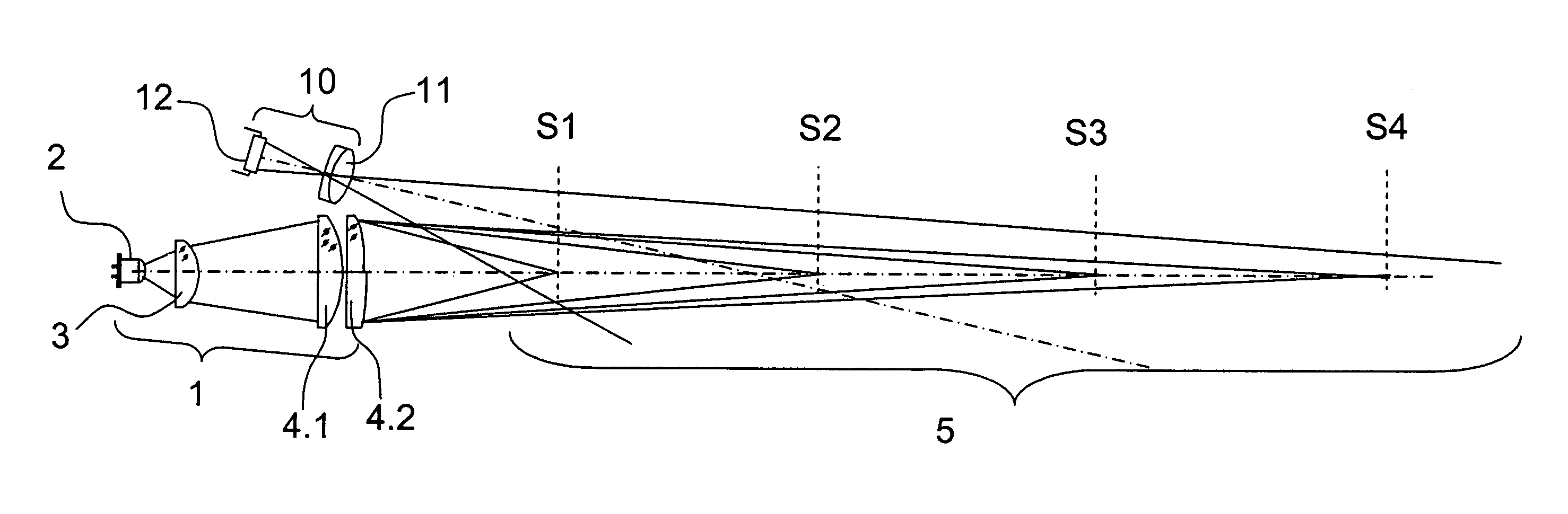
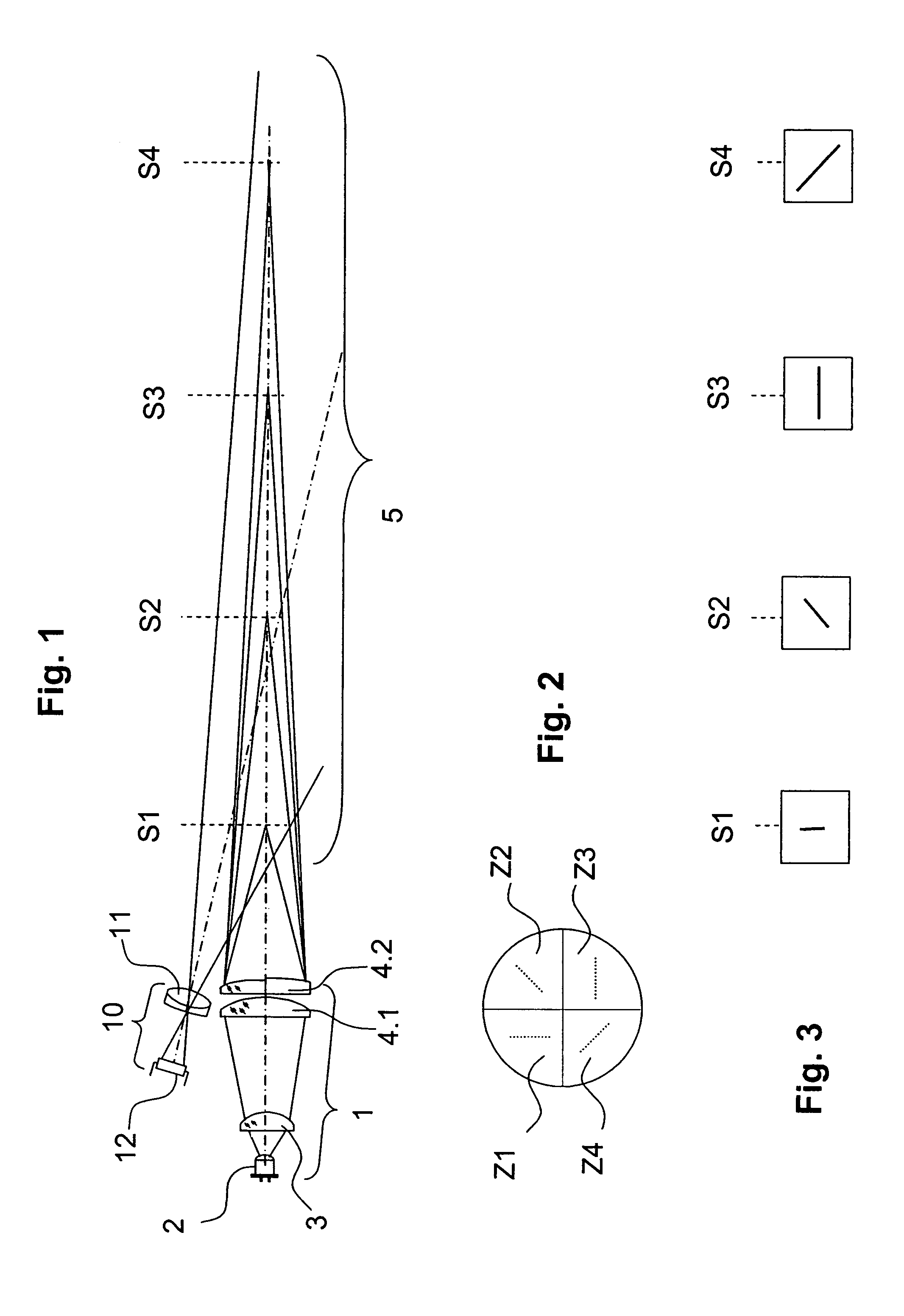
[0022]FIG. 1 schematically illustrates the distance measuring device of the present invention which has a lighting unit 1 and a light receiving unit 10. The lighting unit 1 and the light receiving unit 10 are arranged in close proximity to each other so that the angle between their optical axes is small. However, if desired, a beam splitting mirror or a geometrically uncoupling mirror can be used which permits a positioning of lighting unit 1 and light receiving unit 10 so that their optical axes outside the distance measuring device extend parallel to each other. Lighting unit 1 includes a light source 2 and a transmitting optic that is aligned therewith. Light source 2 is preferably a semiconductor light source such as a laser or an LED. However, other light sources can also be employed. In the embodiment illustrated in FIG. 1, the transmitting optics are formed by a collimating lens 3 and a beam forming optic arrangement in the form of a transmitting lens 4.1 and a multi-zone len...


PUM


Abstract

A distance measurement device which has a lighting unit, including transmission optics with light beam forming optics. Illumination patterns are formed on objects in the measurement area which differ depending on the distances from the measurement device. A light receiving unit is arranged adjacent the lighting unit and generates an image of the illuminated object via receiving optics. A detector array is located in the image plane of the receiving optics which converts the optical image into corresponding electrical signals. The signals from the detector area are forwarded to a signal processing unit that is capable of generating information concerning the distance between the object and the distance measurement device from the detected illumination pattern and the signals generated by the detector.

Description

RELATED APPLICATIONS[0001]This application is based on and claims the priority of German patent application DE 10 2006 034 926.1 filed Jul. 28, 2006, which is incorporated herein by reference.BACKGROUND OF THE INVENTION[0002]The present invention concerns an optoelectronic distance measurement device for determining the distance of an object in a measurement area from the device.[0003]Such optoelectronic distance measurement devices are used, for example, for optoelectronically determining the distance from the measurement device of an object that is located in a given measurement area. This allows one, for example, to classify objects on a conveyor band on the basis of their size or to determine the fill level of containers, and to forward this information to a central monitoring location or unit.[0004]Known optoelectronic distance measurement devices capable of making such distance determinations can be roughly divided into two groups based on their underlying technology. One grou...

Claims


Application Information

Patent Timeline
Patent Type & Authority Patents(United States)
IPC IPC(8): G01C3/08
CPCG01S17/46
Inventor MACK, STEFAN
Owner SICK AG
Why Eureka
Try Eureka