Optimization of combinational logic synthesis through clock latency scheduling

a logic synthesis and clock latency scheduling technology, applied in the field of logic optimization and clock latency scheduling, can solve the problems of affecting the optimization of combinational logic paths in circuit design may be limited by critical, and the design of integrated circuits are often quite unbalanced in terms of timing criticality of logic paths, so as to achieve the effect of optimizing the circuit design

Inactive Publication Date: 2009-07-07
CADENCE DESIGN SYST INC
View PDF2 Cites 22 Cited by
  • Summary
  • Abstract
  • Description
  • Claims
  • Application Information

AI Technical Summary

Benefits of technology

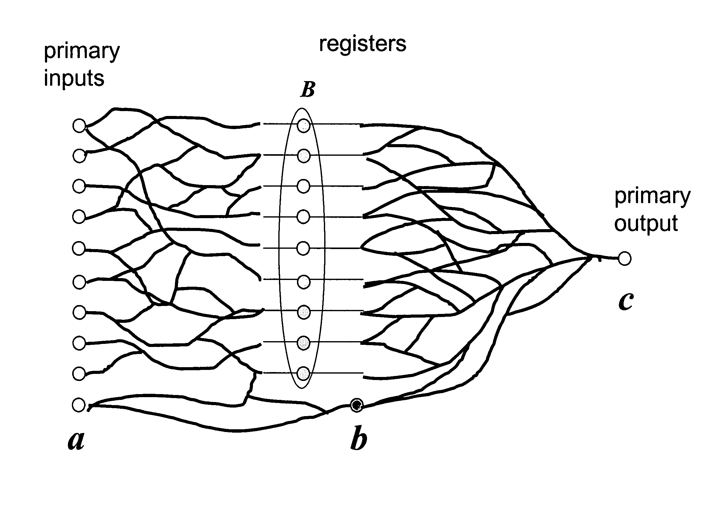
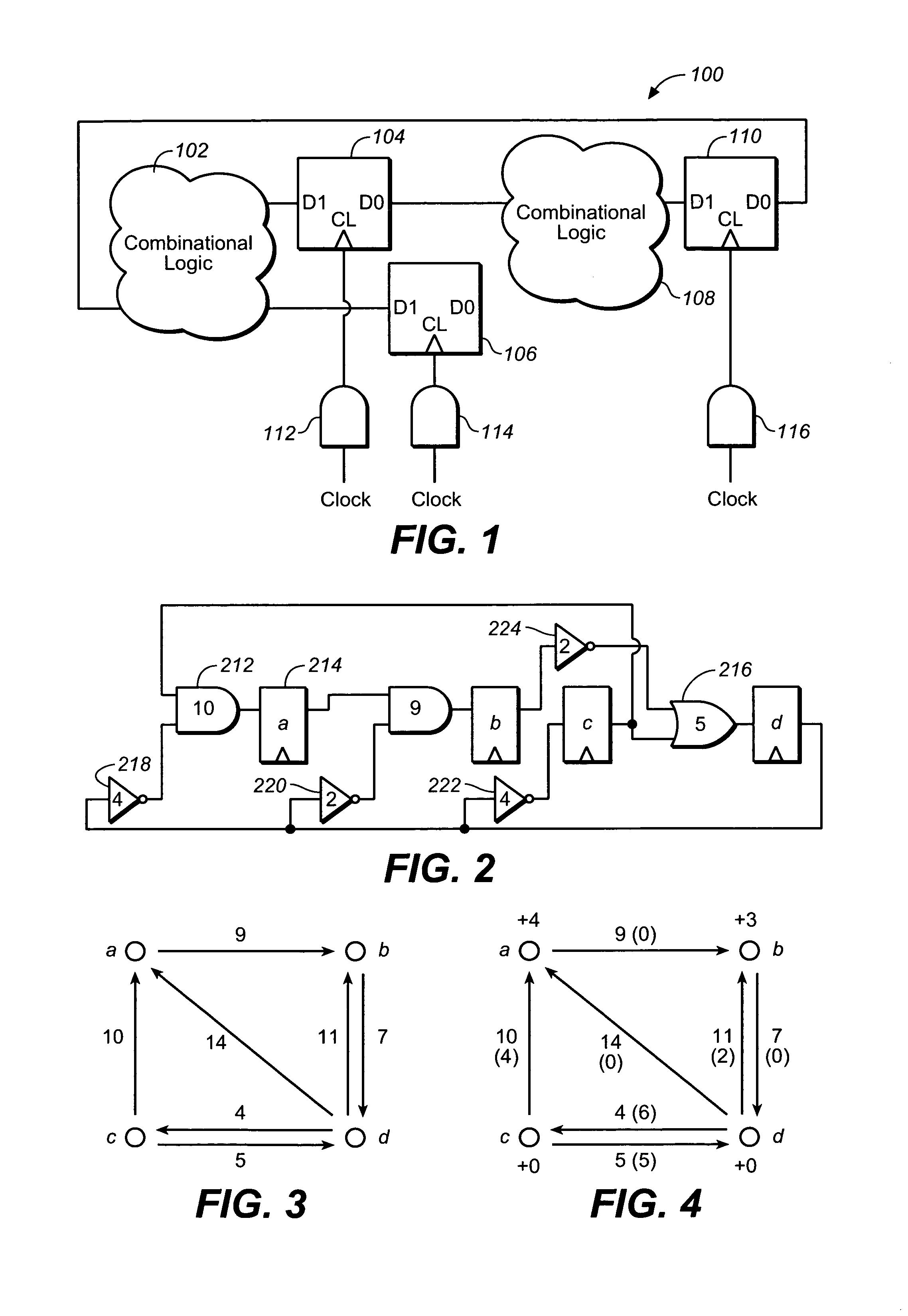
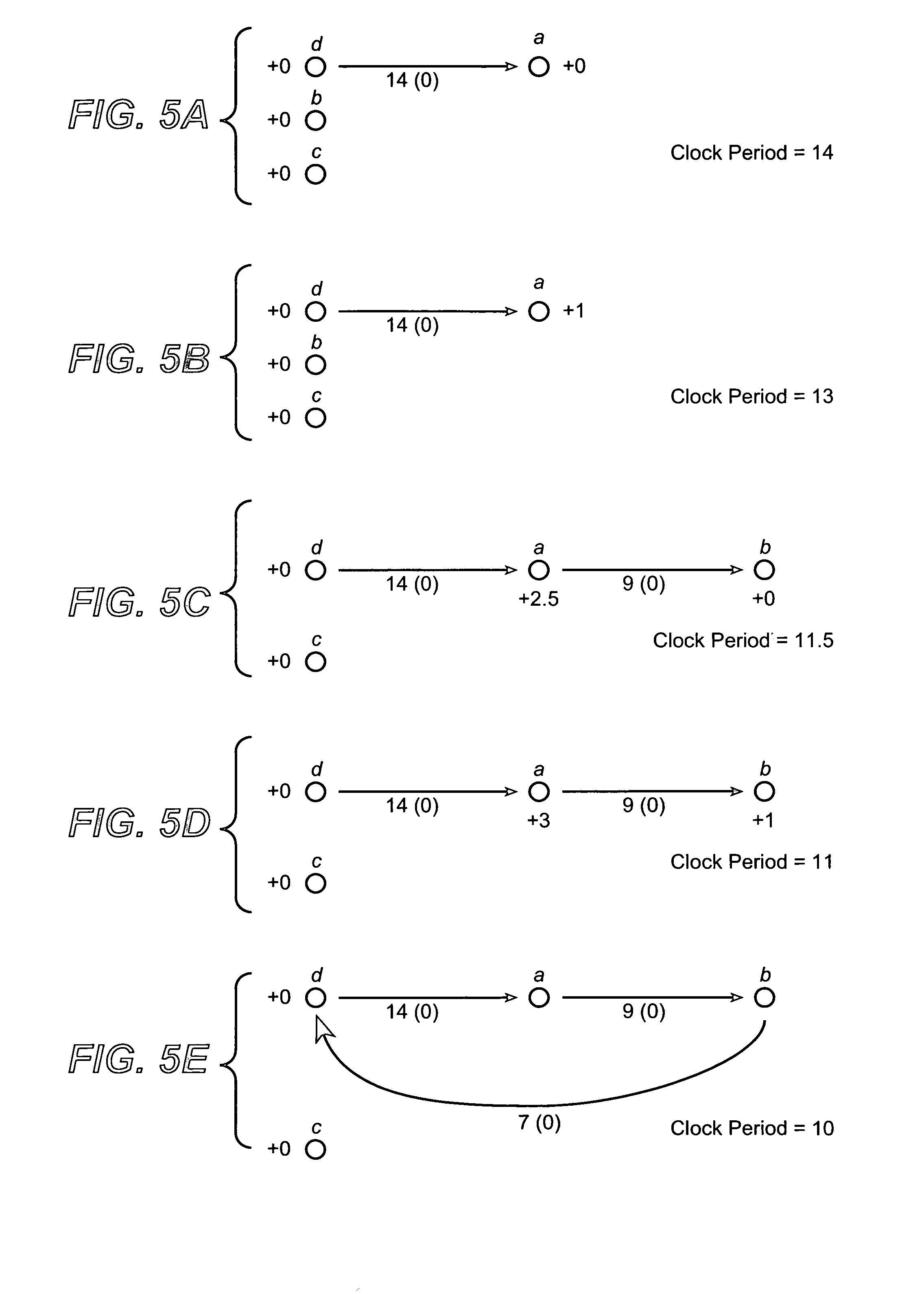
[0010]In one aspect of the invention, a method of optimizing a design of an integrated circuit is provided. An iteration of a logic optimization process is performed that at least partially optimizes a circuit design such that there is slack remaining in one or more combinational logic paths in the circuit design following the iteration. A clock latency scheduling process is performed that respectively distributes the remaining slack of one or more respective combinational logic paths in the circuit design across respective registers in the circuit design. Another iteration of the logic optimization process is performed that uses at least a portion of the distributed slack to further optimize the circuit design.

Problems solved by technology

Integrated circuit designs often are quite unbalanced with respect to the timing criticality of their logic paths.
That is, optimization of combinational logic paths in a circuit design may be limited by critical paths even though there may be room for additional optimization of sequential paths in the same design.
As a result traditional synthesis techniques may overdesign combinational logic paths to speed up gates through resizing, for example, which may incur a significant cost in area, even when there is slack in sequential paths in the design.
Typical retiming does not address the problem of overdesigned combinational logic paths since commonly used formulations assume a fixed gate timing.
However, it still applies hard paths partitioning and thus may not predictably balance all slacks.

Method used


Image

  • Optimization of combinational logic synthesis through clock latency scheduling
  • Optimization of combinational logic synthesis through clock latency scheduling
  • Optimization of combinational logic synthesis through clock latency scheduling

Examples


Embodiment Construction

[0027]The following description is presented to enable any person skilled in the art to make and use the invention, and is provided in the context of particular applications and their requirements. Various modifications to the preferred embodiments will be readily apparent to those skilled in the art, and the generic principles defined herein may be applied to other embodiments and applications without departing from the spirit and scope of the invention. Moreover, in the following description, numerous details are set forth for the purpose of explanation. However, one of ordinary skill in the art will realize that the invention might be practiced without the use of these specific details. In other instances, well-known structures and devices are shown in block diagram form in order not to obscure the description of the invention with unnecessary detail. Moreover, in order to simplify the description, certain identical components have been labeled with identical reference numerals. ...


PUM


Abstract

In optimizing a design of an integrated circuit, an iteration of a logic optimization process is performed that at least partially optimizes a circuit design such that there is slack remaining in one or more combinational logic paths in the circuit design following the iteration. A clock latency scheduling process is performed that respectively distributes the remaining slack of one or more respective combinational logic paths in the circuit design across respective registers in the circuit design. Another iteration of the logic optimization process is performed that uses at least a portion of the distributed slack to further optimize the circuit design.

Description

CROSS-REFERENCE TO RELATED APPLICATION[0001]This application is a continuation-in-part of pending application Ser. No. 11 / 144,371 filed Jun. 2, 2005.BACKGROUND OF THE INVENTION[0002]1. Field of the Invention[0003]The invention relates generally to the design of integrated circuits, and more particularly, to logic optimization and clock latency scheduling during integrated circuit design.[0004]2. Description of the Related Art[0005]Integrated circuit designs often are quite unbalanced with respect to the timing criticality of their logic paths. That is, optimization of combinational logic paths in a circuit design may be limited by critical paths even though there may be room for additional optimization of sequential paths in the same design. As a result traditional synthesis techniques may overdesign combinational logic paths to speed up gates through resizing, for example, which may incur a significant cost in area, even when there is slack in sequential paths in the design.[0006]S...

Claims


Application Information

Patent Timeline
Patent Type & Authority Patents(United States)
IPC IPC(8): G06F17/50
CPCG06F17/505G06F30/327
Inventor ALBRECHT, CHRISTOPHKUEHLMANN, ANDREASSEIBERT, DAVIDRICHTER, SASCHA
Owner CADENCE DESIGN SYST INC
Why Eureka
Try Eureka