Engine fuel pump control apparatus

a control apparatus and fuel pump technology, applied in the direction of electrical control, process and machine control, instruments, etc., can solve the problems low noise, and infrequent use of engine in high load regions, so as to reduce the occurrence of subordinate fuel pump seizing, prevent seizing, and suppress the operation of fuel pump sound

Active Publication Date: 2009-07-14
NISSAN MOTOR CO LTD
View PDF12 Cites 4 Cited by
  • Summary
  • Abstract
  • Description
  • Claims
  • Application Information

AI Technical Summary

Benefits of technology

[0011]The present invention was conceived in view of this problem associated with the existing technology. One object is to reduce the occurrence of fuel pump seizing while suppressing the operating sound of the fuel pumps when they are operated in order to prevent seizing.

Problems solved by technology

However, with this fuel pump control apparatus, there is also a possibility that the subordinate fuel pump could seize because, depending on the driver of the vehicle, the frequency at which the engine is used in a high load region might be very infrequent.
Since the engine noise is comparatively low when the fuel pumps are driven in this manner, the operating sound of the pumps is noticeable as noise to passengers in the vehicle.

Method used


Image

  • Engine fuel pump control apparatus
  • Engine fuel pump control apparatus
  • Engine fuel pump control apparatus

Examples


first embodiment

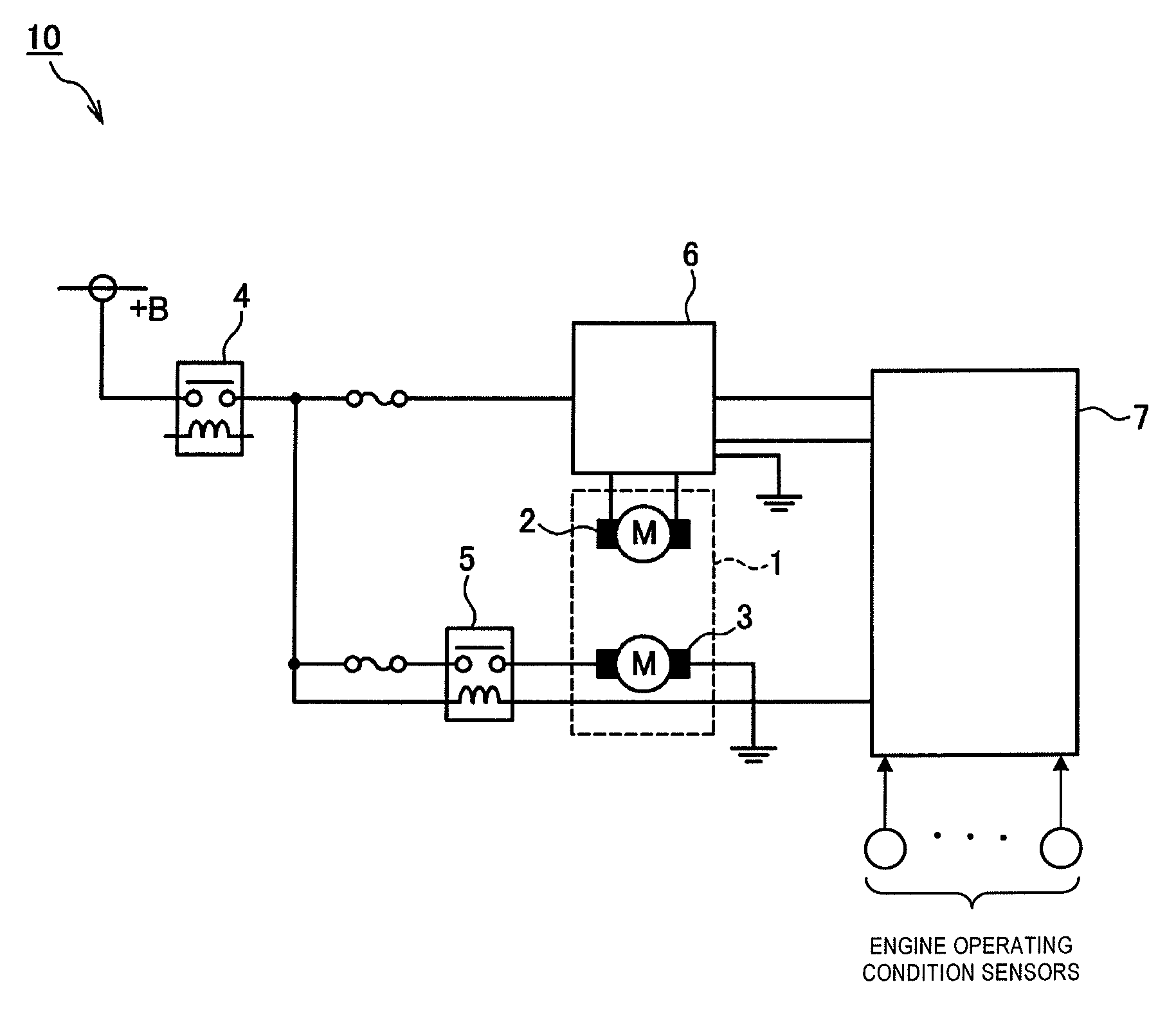
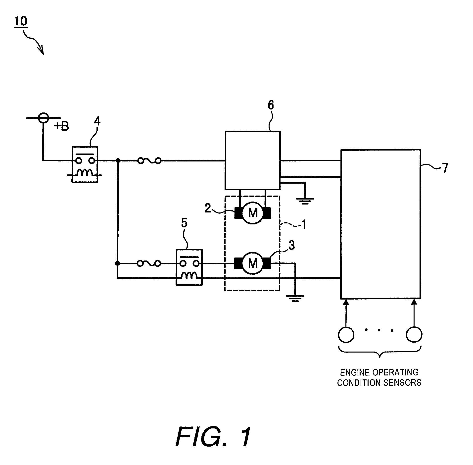
[0025]Referring initially to FIG. 1, an engine fuel pump control apparatus 10 is schematically illustrated in accordance with a first embodiment. As shown in FIG. 1, the engine fuel pump control apparatus 10 basically comprises a fuel tank 1, a main fuel pump 2, a subordinate fuel pump 3, an ignition relay 4, a subordinate pump drive relay 5, a pump flow rate control device 6, and a controller 7. The fuel tank 1 stores fuel to be supplied to an engine via the main fuel pump 2 and the subordinate fuel pump 3.

[0026]The main fuel pump 2 and the subordinate fuel pump 3 are fuel pumps provided inside the fuel tank 1. The main fuel pump 2 and the subordinate fuel pump 3 serve to pump fuel to the engine. The main fuel pump 2 is always driven while the engine is running.

[0027]Basically, the engine fuel pump control apparatus 10 supplies fuel to the engine by controlling the main fuel pump 2 when an engine operating condition indicates that an amount of fuel required by the engine is small a...

second embodiment

[0059]A forced drive control for the subordinate fuel pump 3 that is in accordance with a second embodiment will now be explained with reference to FIG. 6. This embodiment differs from the first embodiment in that forced driving of the subordinate fuel pump 3 is prohibited during purging of evaporated fuel gas. The second embodiment will be explained chiefly based on its differences with respect to the first embodiment. Parts of the second and subsequent embodiments that achieve the same functions as the parts of the first embodiment are indicated with the same reference numerals and explanations thereof are omitted for the sake of brevity.

[0060]There are times when the controller 7 purges adsorbed fuel vapor from a canister into an intake passage by executing a purge control while the engine is running. When the purge control is executed, the amount of fuel delivered to the engine increases in accordance with the amount of purged fuel vapor and the air fuel ratio shifts to a richer...

third embodiment

[0067]A forced drive control for the subordinate fuel pump 3 that is in accordance with a third embodiment will now be explained with reference to FIG. 7. The third embodiment differs from the first embodiment in that a fuel injection pulse width applied to the fuel injectors is shortened during forced drive control of the subordinate fuel pump 3. The third embodiment will be explained chiefly based on its differences with respect to the first embodiment.

[0068]As explained previously, during the forced drive control of the subordinate fuel pump 3, the output fuel quantity increases in accordance with the output of the subordinate fuel pump 3. Since the control fuel pressure of the pressure regulator increases due to the increased output fuel quantity, the fuel injection quantity, will also increase if the injection time of the fuel injectors is left the same.

[0069]Therefore, in this embodiment, the valve open duration of the fuel injectors is shortened during forced driving of the s...


PUM


Abstract

An engine control fuel pump apparatus is provided with a low load fuel pump control section, a high load fuel pump control section and a subordinate pump drive section. The low load fuel pump control section controls a main fuel pump for supplying fuel to an engine when an engine operating condition indicates that the engine is operating with a low load. The high load fuel pump control section controls the main fuel pump and a subordinate fuel pump for supplying fuel to the engine when an engine operating condition indicates that the engine is operating with a high load. The subordinate pump drive section drives the subordinate fuel pump for a prescribed period of time when a rotational speed of the engine is equal to or higher than a prescribed rotational speed while the engine is operating in an low load operating region in which the low load fuel pump control section controls the main fuel pump for supplying fuel to the engine.

Description

CROSS-REFERENCE TO RELATED APPLICATIONS[0001]This application claims priority to Japanese Patent Application No. 2007-110442, filed on Apr. 19, 2007. The entire disclosure of Japanese Patent Application No. 2007-110442 is hereby incorporated herein by reference.BACKGROUND OF THE INVENTION[0002]1. Field of the Invention[0003]The present invention generally relates to a fuel pump control apparatus for an engine. More specifically, the present invention relates to an engine fuel pump control apparatus that controls a main fuel pump and a subordinate fuel pump.[0004]2. Background Information[0005]A conventional fuel pump control apparatus has a main fuel pump arranged in a main fuel tank and a subordinate fuel pump arranged in a subordinate fuel tank for supplying fuel to an engine (e.g., Japanese Laid-Open Patent Publication No. 2003-293877). This conventional fuel pump control apparatus normally uses fuel from the main fuel tank. A driver operated switch is provided such that the driv...

Claims


Application Information

Patent Timeline
Patent Type & Authority Patents(United States)
IPC IPC(8): F02M37/04
CPCF02D41/34F02M37/18F02D41/3082F02D41/003F02D41/20Y02T10/44Y02T10/40F02D41/00F02M37/08
Inventor YAHATA, TAKANOBU
Owner NISSAN MOTOR CO LTD
Why Eureka
Try Eureka