Electronic braking and energy recycling system associated with DC brushless motor

a brushless motor and electric braking technology, which is applied in the direction of motor/generator/converter stoppers, dynamo-electric converter control, dc motor stoppers, etc., can solve the problems of increasing the current flow through the windings very quickly, the above mechanism is incapable of providing a sufficient torsion for braking of the vehicle, and the electronic braking mechanism is a sort of wasting electronic energy. , to achieve the effect of smoothly and reliably

Inactive Publication Date: 2009-07-14
WIZ ENERGY TECH
View PDF4 Cites 3 Cited by
  • Summary
  • Abstract
  • Description
  • Claims
  • Application Information

AI Technical Summary

Benefits of technology

[0011]The present invention discloses an electronic braking and energy recycling system associated with a direct current (DC) brushless motor, which can particularly achieves a controllable inverse torsion or damping force for motor braking by using a set of simple gate signals with positive and negative cycles for controlling operations of respective MOSFETs on upper and lower-side branches (six combinations in total), which is not interfered by multi-phase coils, and thus obtains a maximum proportion of dynamic power recycling, without the need of altering any of a hardware structure of the conventional system.
[0012]In accordance with the present invention, the electronic braking and energy recycling system associated with direct current (DC) brushless motor is characterized in that when an electronic braking task is launched, a phase voltage occurred in an inverse mode is applied onto a motor coil corresponding thereto and a gate voltage signal with positive and negative cycles is used to control an upper-side and lower-side branches to switch, so as to redirect a current flown through the motor back to a power source end. In this invention, a controllable inverse torsion is achieved, enabling an electrical machine to be braked smoothly and reliably when necessary. As such, the dynamic power of the motor can be recycled at a maximum rate and thus the purpose of energy recycling is achieved. In addition, no complex circuitry configuration owing to the multi-phase coils is required.

Problems solved by technology

Therefore, how to make the dynamic power efficiently conversed into electrical energy, which can be then restored back to a battery, as braking the vehicle via the same DC brushless motor is apparently an essential issue for the current research and development.
When the motor is at the lower speed mode, the induced voltage on the motor coil is also relatively lower (ε_motor×Δt_ON=L_motor×Δi_motor), making the above mechanism incapable of providing a sufficient torsion for braking of the vehicle.
Therefore, such an electronic braking mechanism is a sort of wasting electronic energy to resist the motor rotation.
Due to the added current with the same direction as the one of the induced electromotive force, the current flown through the windings increases very quickly and there is no sufficient releasing duty for both of the electrical energy from the power system and the induced voltage from the rotating motor.
Thus, the conventional brush control system can only provide the braking function without appropriately saving the supplied electrical energy.
As shown, the motor has three-phase windings, which are inherently difficult to be used for electronic braking or energy recycling.
However, it is not allowable for any capacity difference between cell individuals of the battery.
Miserably, the same problems are also encountered.
At this time, the braking function can only be achieved by resorting to a mechanical design.
More importantly, this braking mechanism can only be effective under the situation where the other two phases of the motor does not produce any other induced current owing to the induced voltage of the subject phase and thus interfere the control mechanism as previously designed.
Therefore, there are still many problems to be overcome in the conventional technology.

Method used


Image

  • Electronic braking and energy recycling system associated with DC brushless motor
  • Electronic braking and energy recycling system associated with DC brushless motor
  • Electronic braking and energy recycling system associated with DC brushless motor

Examples


Embodiment Construction

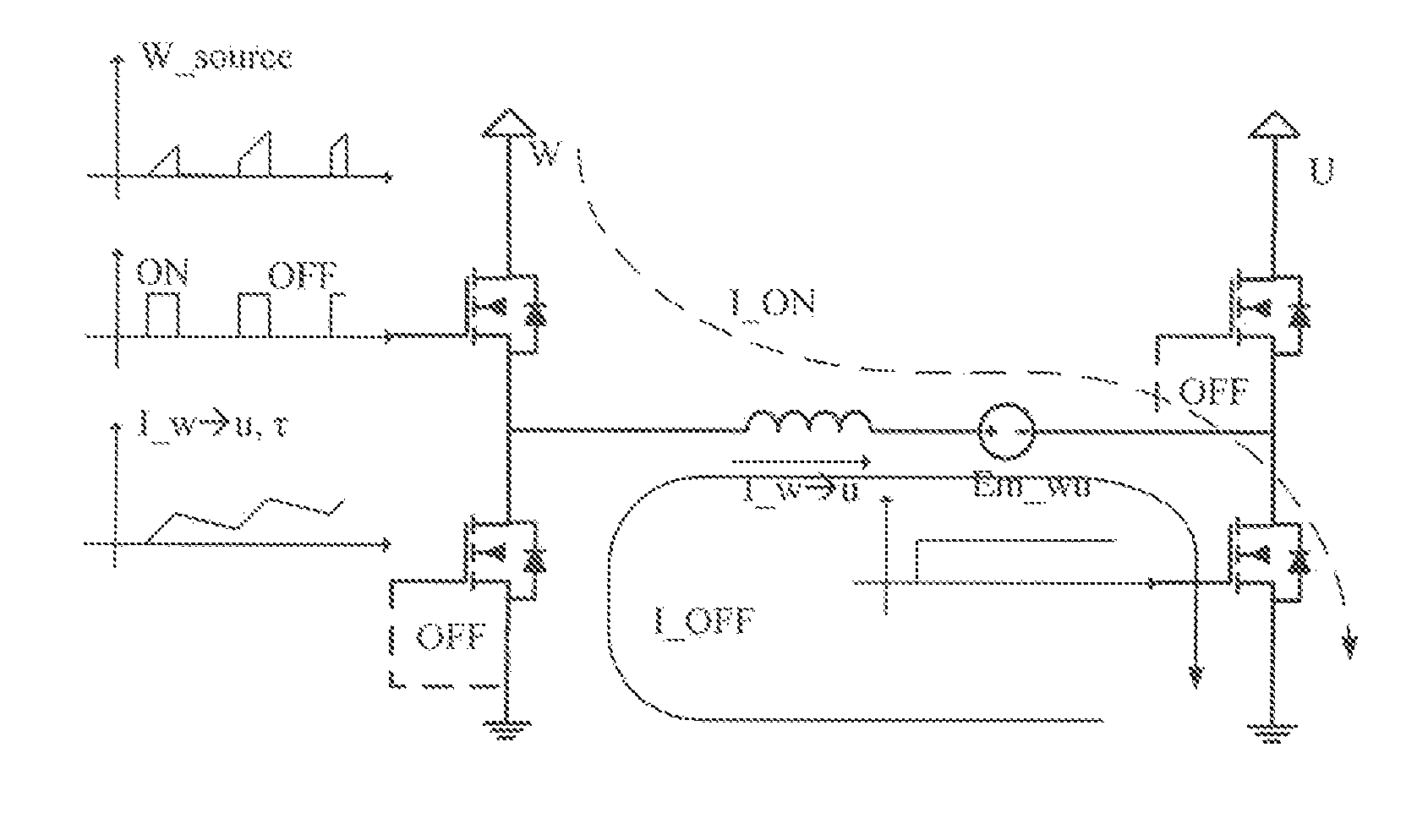
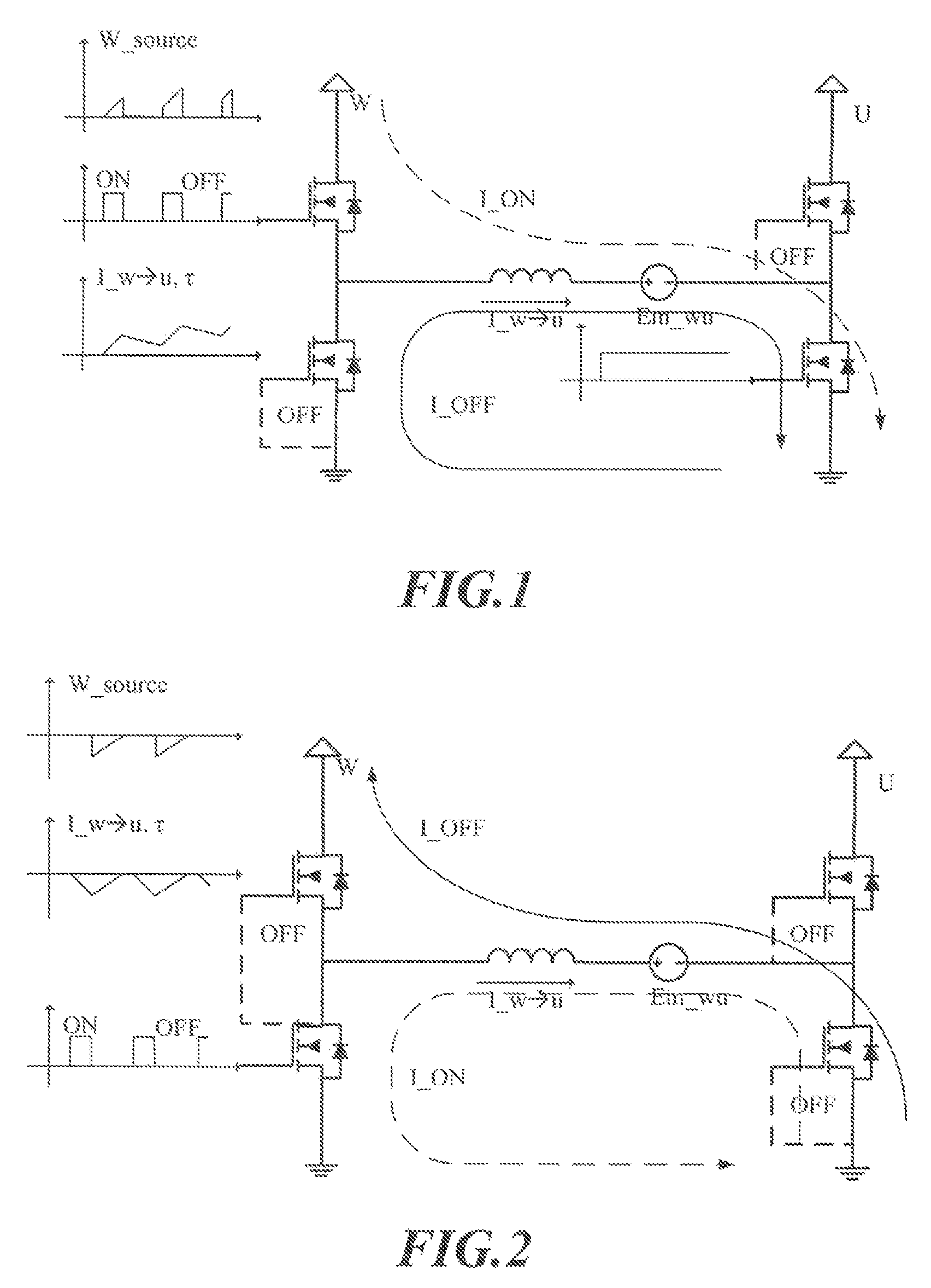
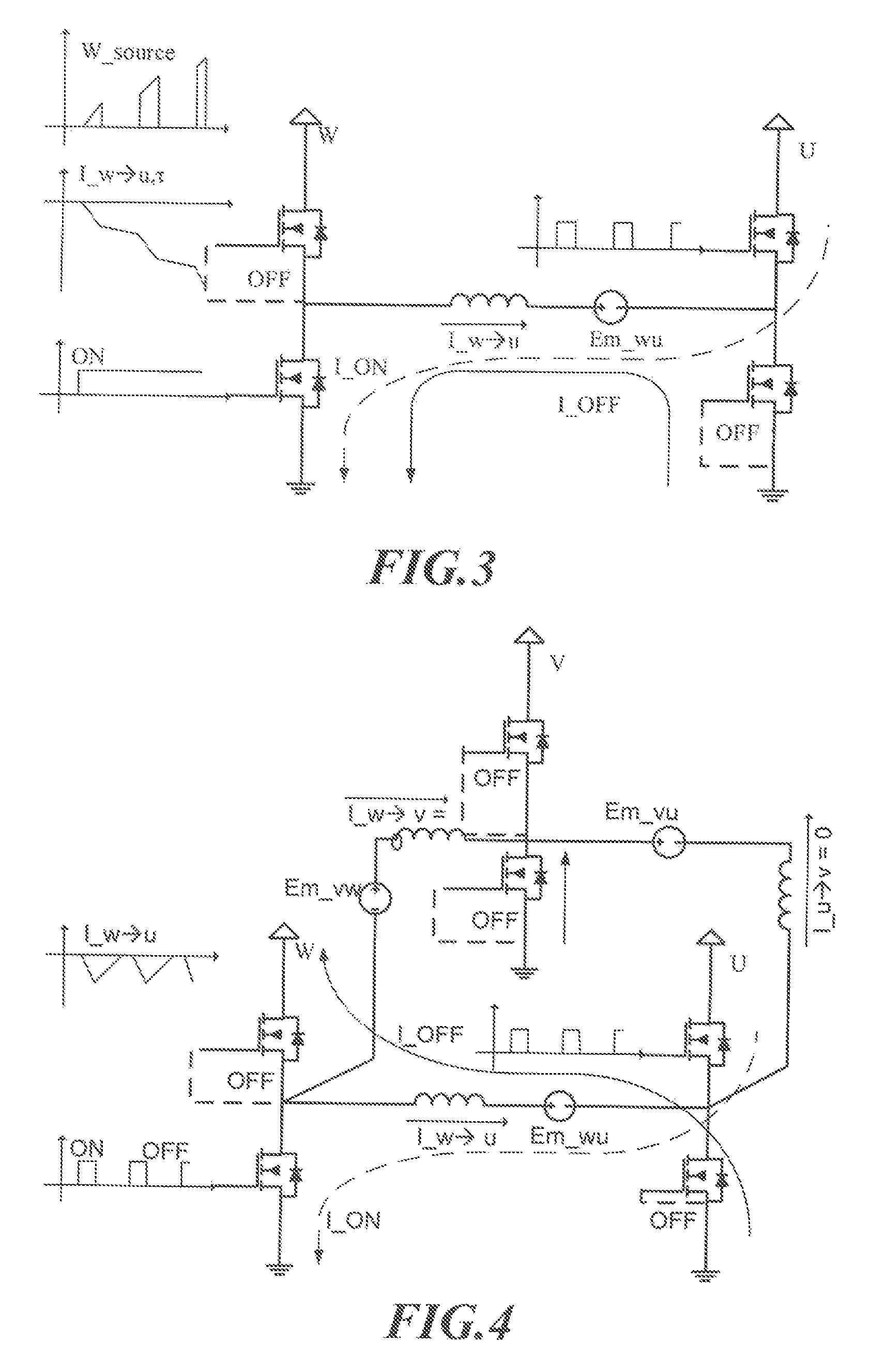
[0024]The present invention discloses an electronic braking and energy recycling system associated with DC brushless motor, which can provide an inverse torsion-based braking function by using a conversion of a gate voltages under the condition without altering the conventional motor controller and any hardware configuration of the motor. Further, the inventive system can achieve the maximum recycling ratio for the dynamic power of the motor without being interfered with the multi-phase coil.

[0025]Referring to FIG. 7, the DC brushless motor is shown therein, in which a current is shown as flowing through a coil of the motor with the flow direction thereof also indicated. When the electronic braking system is launched, a controller applies a voltage associated with an inverse mode onto the indicated motor coil. At this time, the current flown through the motor coil has the relationship with other parameters related to the motor (Voltage-Time Law: V_motor×Δt_ON=L_motor×Δi_motor):

(εmot...


PUM


Abstract

An electronic braking and energy recycling system associated with a direct current (DC) brushless motor, characterized in that when an electronic braking task is launched, a phase voltage occurred in an inverse mode is applied onto a motor coil corresponding thereto and a gate voltage signal with positive and negative cycles is used to control an upper-side and lower-side branches to switch as compared to each other in the system, so as to redirect a current flown through the motor back to a power source end. In this invention, a controllable inverse torsion is achieved, enabling an electrical machine to be braked smoothly and reliably when necessary. As such, a dynamic power of the motor can be recycled at a maximum rate and thus the purpose of energy recycling is achieved. In addition, no complex circuitry configuration owing to the multi-phase coils is required.

Description

BACKGROUND OF THE INVENTION[0001]1. Field of the Invention[0002]The present invention relates to an electronic braking and energy recycling system associated with a direct current (DC) brushless motor, which can achieve a controllable inverse torsion or damping force, for motor braking by using a set of specially defined simple gate signals. Particularly, this present invention can obtain a theoretically maximum recycling proportion of a dynamic power, without the need of altering any hardware structure of the conventional system of this kind.[0003]2. Description of the Prior Art[0004]Earlier electronic brake systems are all developed for the electrical products requiring a constant speed control, such as medical scooter and electro-trailer used in market or factory. All these electrical machines are typically requested with a safe and reliable electronic speed-control mechanism. In this regard, how to provide such electrical products with a smooth and reliable friction in a brake t...

Claims


Application Information

Patent Timeline
Patent Type & Authority Patents(United States)
IPC IPC(8): H02P3/14
CPCH02P25/021H02P3/18H02P25/024
Inventor SHU, YING-HAWLEE, KUO-MINGMA, BIN-YEN
Owner WIZ ENERGY TECH
Why Eureka
Try Eureka