Motherboard having hard-wired private bus between graphics cards

a graphics card and motherboard technology, applied in the field of graphics systems, can solve the problems of increasing the processing power of graphics cards, increasing the cost of each graphics card having half the pci-e bandwidth, and more expensive than desired

Inactive Publication Date: 2009-07-14
NVIDIA CORP
View PDF15 Cites 21 Cited by
  • Summary
  • Abstract
  • Description
  • Claims
  • Application Information

AI Technical Summary

Benefits of technology

[0043]As previously described, one benefit of the present invention is that the private bus may be used for GPU-to-GPU communication. Investigations by the inventor indicate that there is substantial GPU-to-GPU traffic in typical SLI architecture. In a conventional low-cost implementation of SLI this GPU-to-GPU traffic is typically routed through the chipset. In contrast, one embodiment of the present invention utilizes serial data lanes which would conventionally be unused to form the private bus. For SLI systems in which there is a substantial amount of GPU-to-GPU traffic, the private bus allows a low-cost solution to achieve performance comparable to more expensive solutions. Additionally, as previously described, in one embodiment the private bus is implemented in a fashion that eliminates the need for a switch card 170 and external SLI connector 180, resulting in potential cost savings.

Problems solved by technology

This results in an inherent compromise in that graphics processing power in increased (because of the two GPUs operating in parallel) but at the cost that each graphics card has half of the PCI-E bandwidth that would be the case if it was used alone.
One problem with conventional SLI is that it is more expensive than desired.
In particular, extra components, such as switch cards and SLI connectors, are typically required, increasing the cost.
Another issue is related to performance caused by splitting the PCI-E bandwidth of chip 110 between two graphics cards.
This also has the result of limiting the available bandwidth for GPU-to-GPU traffic that flows through the chipset.
However, in addition to the more expensive chipset that is required, the architecture illustrated in FIG. 3 does not have symmetric data paths 350 and 360 from the CPU 302 to the GPUs.
However, for many market segments the increased performance of adding additional chips or more expensive chips does not justify the additional chip cost.

Method used


Image

  • Motherboard having hard-wired private bus between graphics cards
  • Motherboard having hard-wired private bus between graphics cards
  • Motherboard having hard-wired private bus between graphics cards

Examples


Embodiment Construction

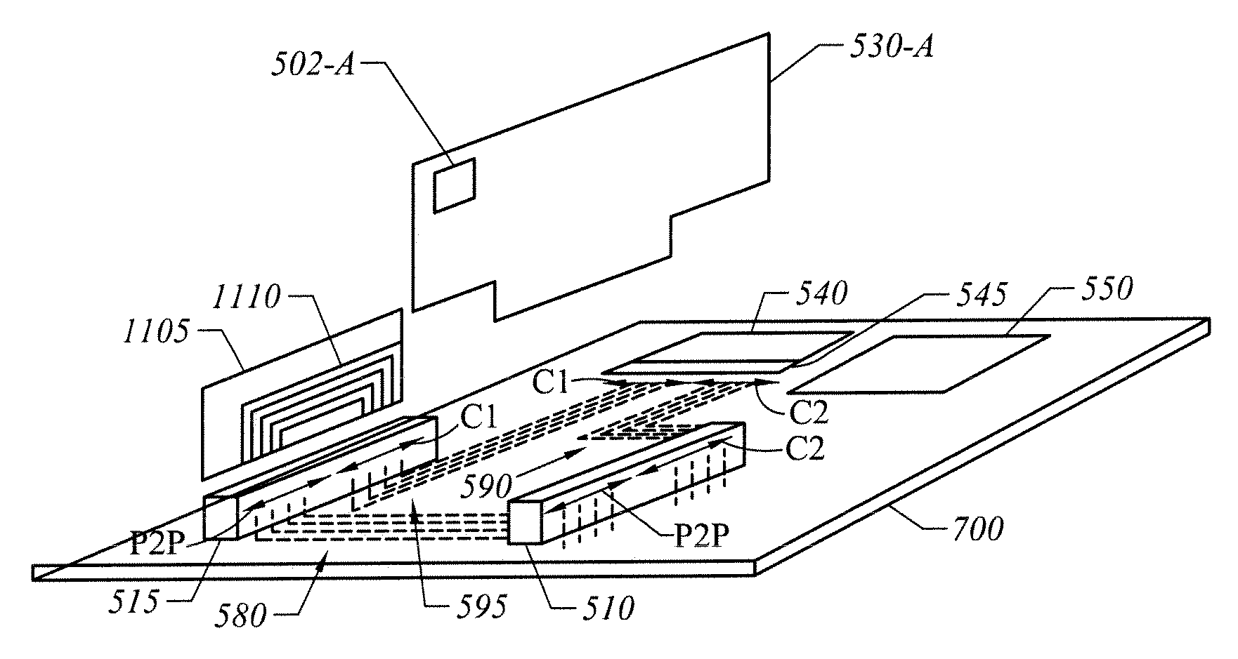
[0028]FIG. 5 is a perspective view of one embodiment of the present invention with some conventional components omitted for clarity and other components not drawn to scale for purposes of illustration. A motherboard 500 includes a chipset which may include a CPU 550 and another chip 540 having a Peripheral Component Interface Express (PCI-E) interface 545. Motherboard 500 has two PCI-E connectors 510 and 515, such as two PCI-E ×16 connectors for receiving graphics cards 530-A and 530-B.

[0029]Graphics cards 530-A and 530-B have PCI-E connector surfaces 535-A and 535-B designed to mate with a corresponding PCI-E connector 510 or 515. Each graphics card 530-A and 530-B has its own respective graphics processing unit (GPU) 502-A and 502-B. Each graphics card 530-A and 530-B includes internal signal paths (not shown) to couple electrical signals from a PCI-E connector surface 535 to a respective GPU 502-A or 502-B.

[0030]An individual PCI-E connector, such as connector 510, has pins 525 a...


PUM


Abstract

A motherboard includes two bus connectors. Each connector has contact positions for a set of serial data lanes. A private bus is formed in the motherboard to couple a subset of the serial data lanes of the two connectors. In one implementation, each connector is a Peripheral Component Interface Express (PCIe) connector with a private bus coupling a subset of the serial data lanes of the two PCIe connectors.

Description

FIELD OF THE INVENTION[0001]The present invention is generally related to graphics systems capable of supporting different numbers of graphics cards for improved performance. More particularly, the present invention is directed towards a private bus to support a cost-effective high performance graphics system.BACKGROUND OF THE INVENTION[0002]Graphics systems are typically implemented as a three-dimensional assembly of different cards (also sometimes called “boards”) that are plugged into a motherboard. The motherboard is the main circuit board of the system and typically includes a central processing unit and other chips that are known as a “chipset.” Additionally, a motherboard includes connectors, ports, and other features for attaching other electronic components.[0003]Referring to FIG. 1, in a conventional graphics system a motherboard 100 includes a chipset that includes, for example, a bridge unit 110 and a central processing unit (CPU) 120. For the purposes of illustration, a...

Claims


Application Information

Patent Timeline
Patent Type & Authority Patents(United States)
IPC IPC(8): G06F13/14
CPCG06F3/14G09G5/363G06F13/409G09G2360/06G06F1/184
Inventor DANILAK, RADOSLAV
Owner NVIDIA CORP
Why Eureka
Try Eureka