Automatic cut lever apparatus

a cutting lever and automatic technology, applied in the direction of railway couplings, railway components, transportation and packaging, etc., can solve the problems of physical strain on the trainman having to lift the cut lever, the risk of injury to the trainman, and the proximity of the trainman

Inactive Publication Date: 2009-07-21
SHARMA & ASSOCS
View PDF11 Cites 2 Cited by
  • Summary
  • Abstract
  • Description
  • Claims
  • Application Information

AI Technical Summary

Benefits of technology

[0011]Yet another object of the present invention is to provide an automatic cut lever apparatus that can be easily retrofitted to existing couplers.
[0012]Still yet another object of the present invention is to provide an automatic cut lever apparatus that significantly minimizes the hazards of uncoupling railroad freight cars.

Problems solved by technology

However, this manual uncoupling of the freight cars is not without several risks of injury to the trainman.
One obvious risk of injury is the physical strain upon the trainman having to lift the cut lever.
Another risk relates to the proximity of the trainman to the train line air hose.
More specifically, upon separation of the freight cars from each other for a sufficient distance, the air pressure that is left in the train line can cause a whip like action of the air hose.
Also, there is a chance that a quick release of air can cause particles of debris to fly.

Method used


Image

  • Automatic cut lever apparatus
  • Automatic cut lever apparatus
  • Automatic cut lever apparatus

Examples


Embodiment Construction

[0018]Prior to proceeding to the more detailed description of the present invention it should be noted that, for the sake of clarity in understanding the invention, identical components having identical functions have been identified with identical reference numerals throughout the several views illustrated in the drawings.

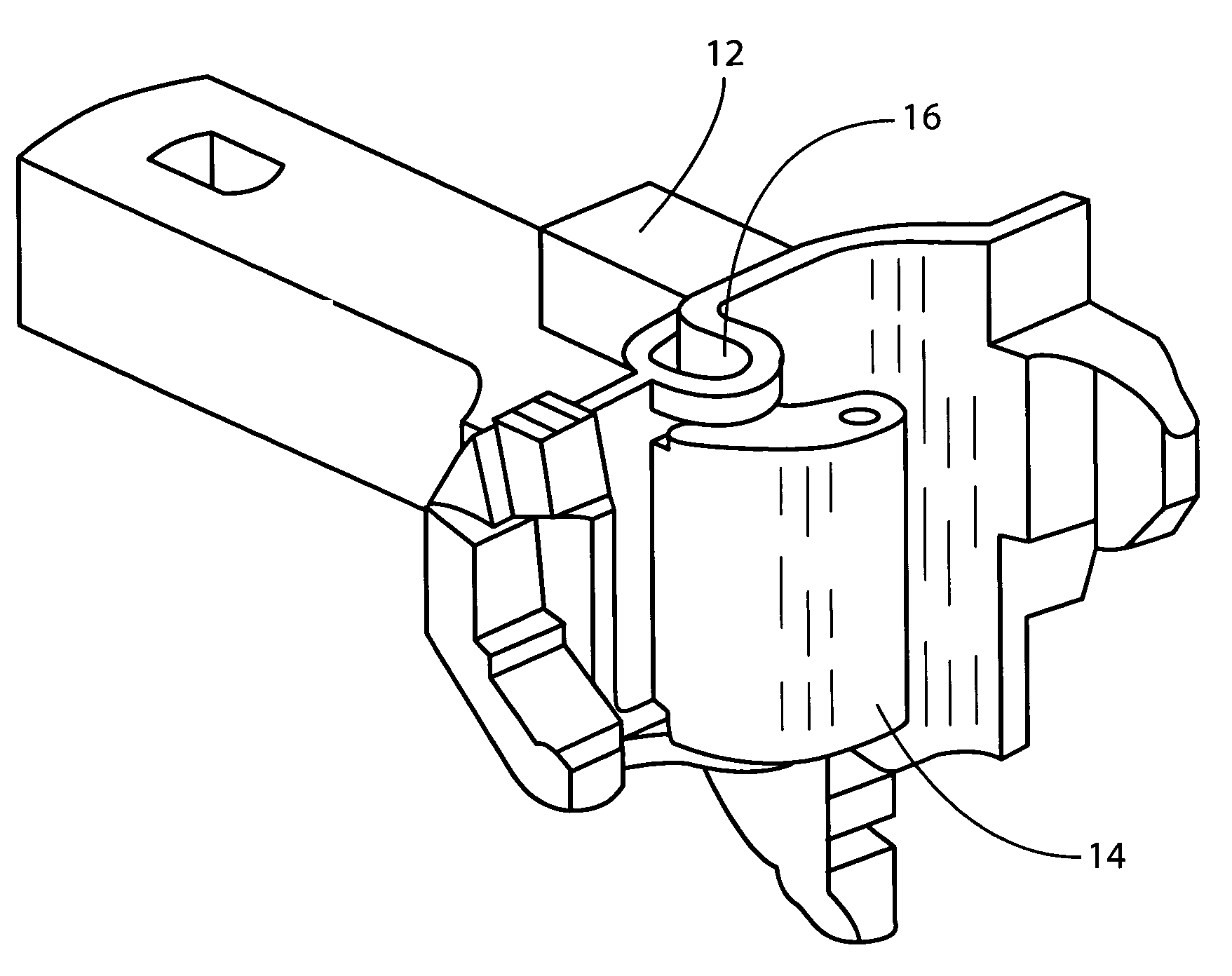
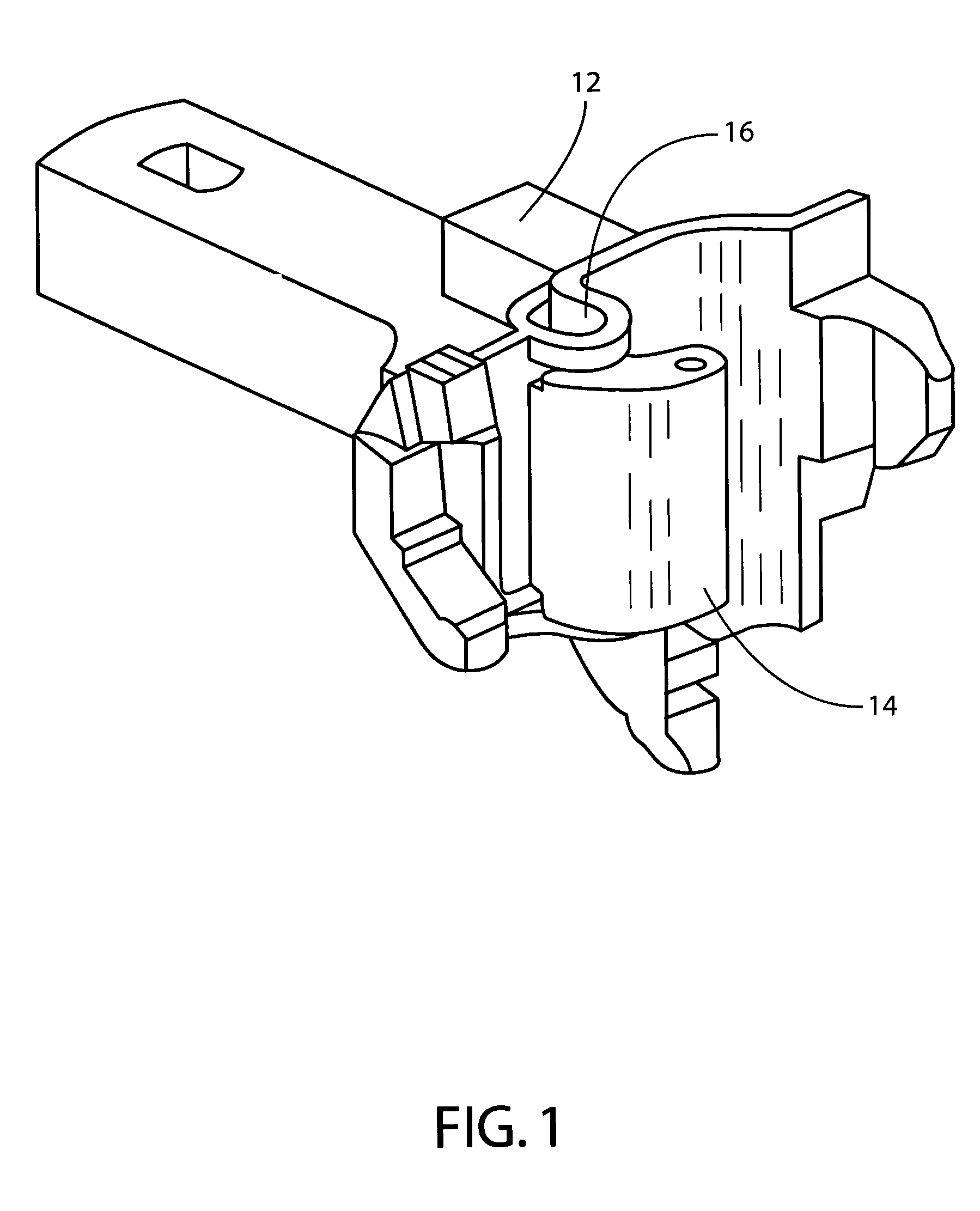
[0019]FIG. 1 illustrates a type of prior art railroad freight car coupler that the present invention can be used with. The coupler includes a coupler body 12, a coupler knuckle 14, a knuckle pin 16 and a lock lift assembly (not shown).

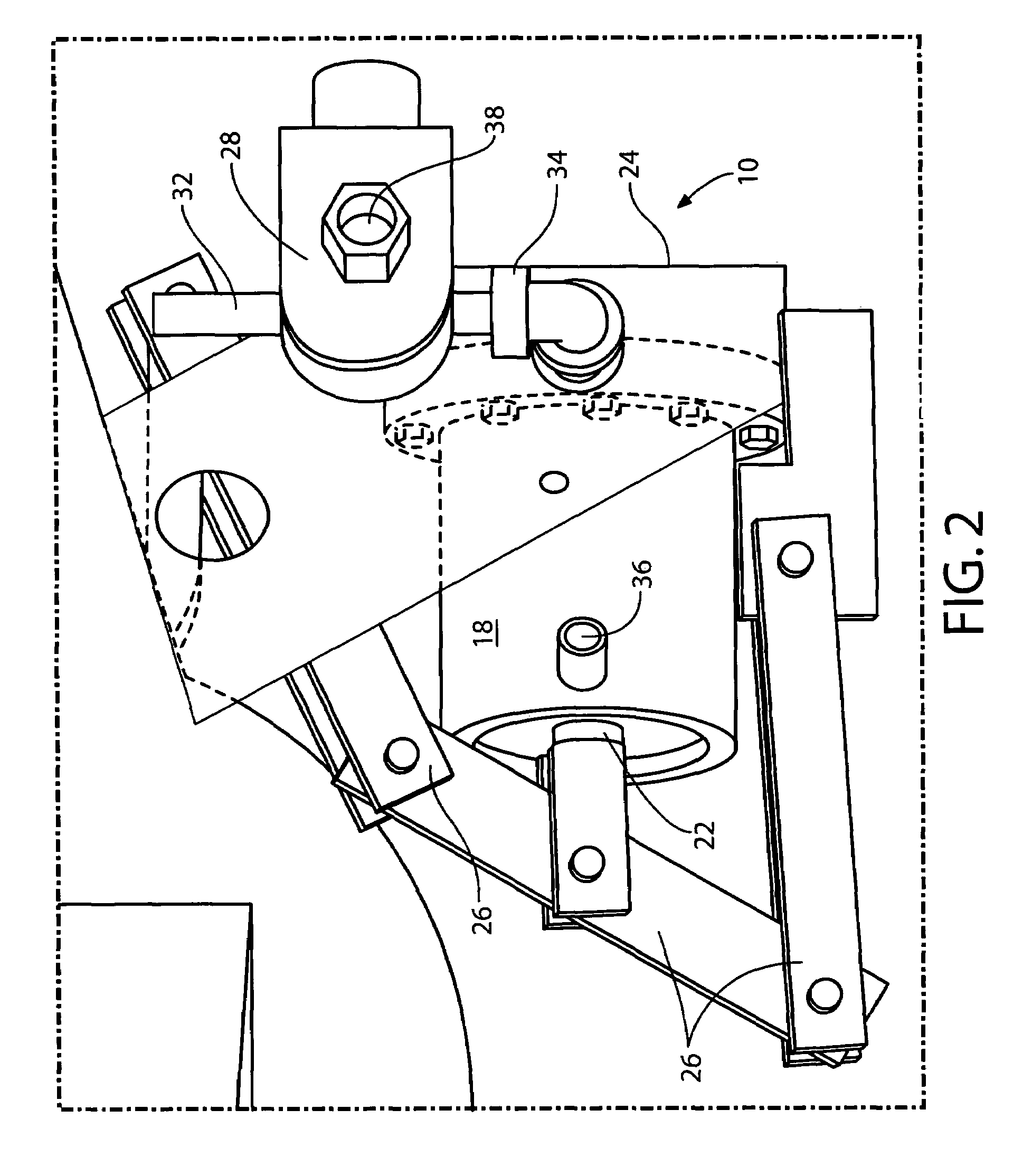
[0020]Now reference is made, more particularly, to the drawing FIGS. 2 and 3. Illustrated therein is an automatic cut lever apparatus, generally designated 10, for actuating the lock lift assembly to automatically at least one of lock and unlock the coupler knuckle 14 of the railroad freight car coupler 12. The automatic cut lever apparatus 10 includes a cylinder member 18 which has a piston 22 disposed therein. The automatic cut lev...


PUM


Abstract

A cut lever apparatus that automatically actuates a lock lift assembly to either lock or unlock a coupler knuckle of a freight car coupler. The apparatus includes a cylinder member having a piston disposed therein. A bracket member is attachable to the freight car coupler to support the cylinder. A linkage member is connected to the piston of the cylinder and the lock lift assembly to convert a lateral motion of the piston to a curvilinear motion of the lock lift assembly to either lock or unlock the coupler knuckle. A valve member is connected to the cylinder for communicating a pressurized fluid to the cylinder when a predetermined signal is sent to the valve and preventing pressurized fluid from entering the cylinder in an absence of the predetermined signal. Pressurized fluid in the cylinder is vented to atmosphere when the valve shuts off supply of pressurized fluid thereto.

Description

CROSS REFERENCE TO RELATED APPLICATION[0001]This application is closely related to and claims priority benefit from U.S. Provisional Patent Application Ser. No. 60 / 738,295 filed on Nov. 18, 2005.FIELD OF THE INVENTION[0002]The present invention relates, in general, to railroad freight car couplers that utilize a manually activated lock lift assembly to lock and unlock a coupler knuckle and, more particularly, the invention relates to an electro-pneumatic cut lever apparatus that is engageable with the lock lift assembly of the railroad freight car coupler to automatically activate the lock lift assembly to lock and unlock the coupler knuckle.BACKGROUND OF THE INVENTION[0003]Prior to the conception and development of the present invention, as is generally well known in the prior art, mechanical couplers used to couple railroad freight cars and locomotives together have been in existence for many years. Some components of the couplers include a coupler body, a coupler knuckle, a knuck...

Claims


Application Information

Patent Timeline
Patent Type & Authority Patents(United States)
IPC IPC(8): B61G1/00
CPCB61G3/08
Inventor KANDOTH-KANNOTH, HARISH K.VITHANI, ANAND R.BRABB, DAVID C.TRENT, ROBERT S.
Owner SHARMA & ASSOCS
Why Eureka
Try Eureka