Clamping mechanism for folder gluer machine

a folder gluer machine and clamping mechanism technology, applied in the field of folder gluer machines, can solve the problems of inconvenient operation, inconvenient clamping mechanism, and difficulty in accurately positioning and clamping the tools of the folder gluer machine with the prior clamping mechanism, and achieve the effect of simple operation and low manufacturing cos

Inactive Publication Date: 2009-07-21
BLANKING SYST
View PDF14 Cites 66 Cited by
  • Summary
  • Abstract
  • Description
  • Claims
  • Application Information

AI Technical Summary

Benefits of technology

[0008]It is a still further object and feature of the present invention to provide a clamping mechanism for clamping multiple tools used by a folder gluer machine that is inexpensive to manufacture and simple to operate.
[0015]A friction disc may be positioned between the first and second clamps. The friction disc prevents rotation of the first and second clamps with the clamping structure in the clamping position. The first clamp includes at least one contact pad projecting into the first clamping cavity. Similarly, the second clamp includes at least one contact pad projecting into the second clamping cavity. The first clamp also includes first and second connection hooks for interconnecting the upper clamping element and the lower clamping element of the first clamp. Likewise, the second clamp includes first and second connection hooks for interconnecting the upper clamping element and the lower clamping element of the second clamp.
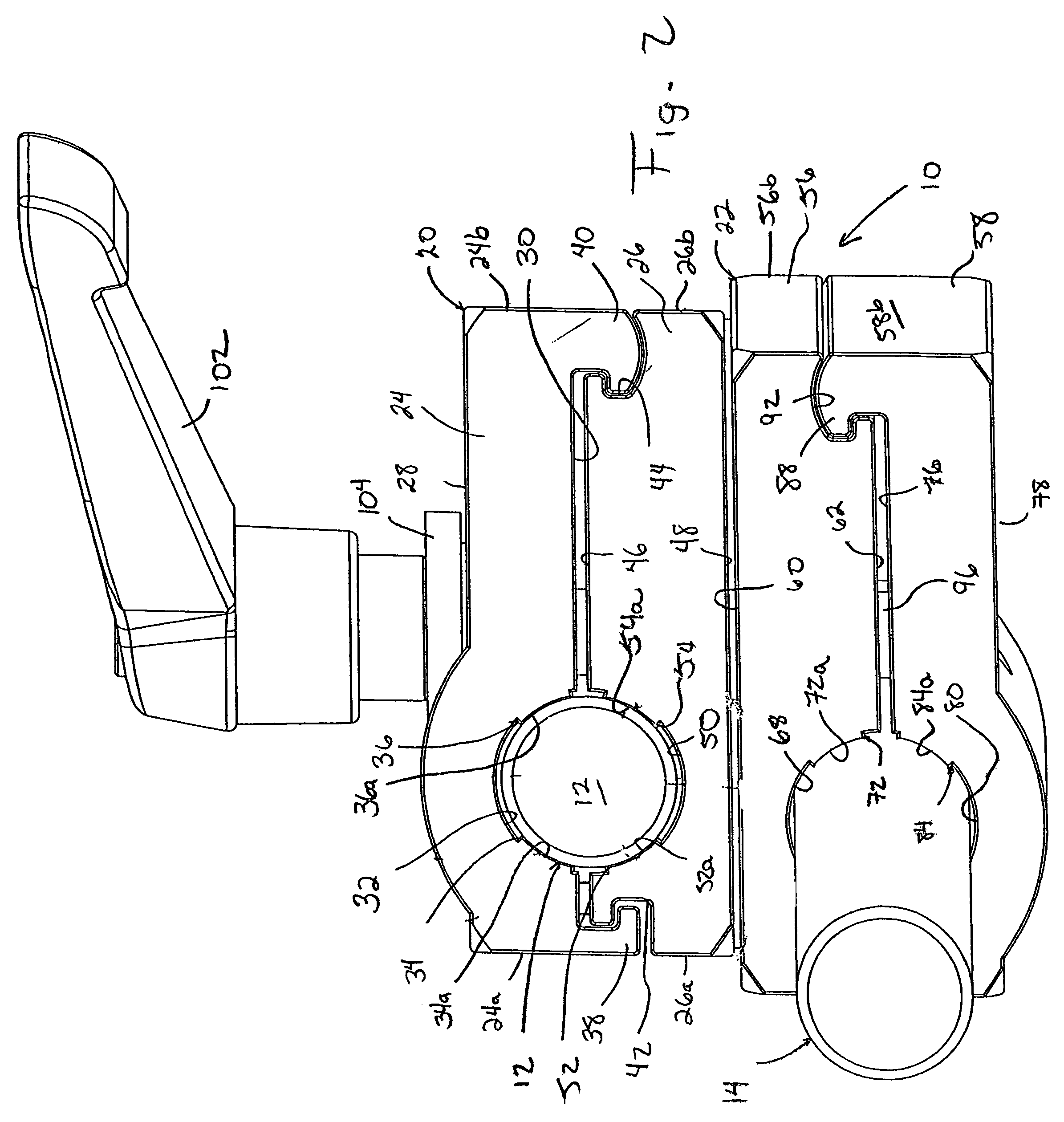
[0027]Lower clamping element 58 of lower clamp 22 includes inner surface 76 and outer surface 78. Inner surface 76 includes an arcuate surface portion 80 that partially defines the clamping cavity within lower clamp 22. Contact pads 82 and 84 project from arcuate surface 80 and terminate at corresponding contact areas 82a and 84a, respectively. Lower clamping element of lower clamp 22 further includes connection hooks 86 and 88 projecting from opposite sides 58a and 58b of lower clamp element 58 of lower clamp 22. Connection hooks 86 and 88 are adapted for receipt in corresponding recesses 90 and 92 in sides 56a and 56b of upper clamping element 56 of lower clamp 22. Recess 90 in side 56a of upper clamping element 56 of lower clamp 22 allows for limited vertical movement of connection hook 86 of upper clamping element 58 to allow for tool 14 to be inserted into and removed from the clamping cavity within lower clamp 22.
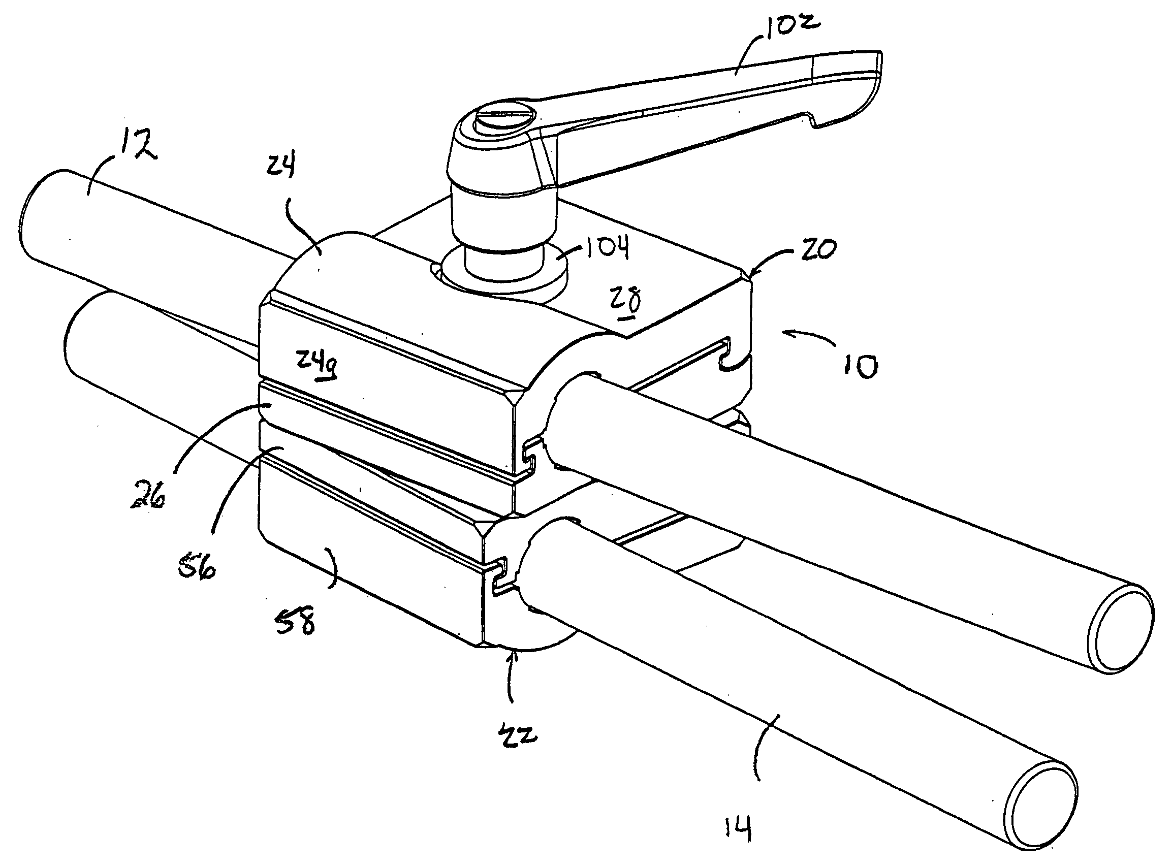
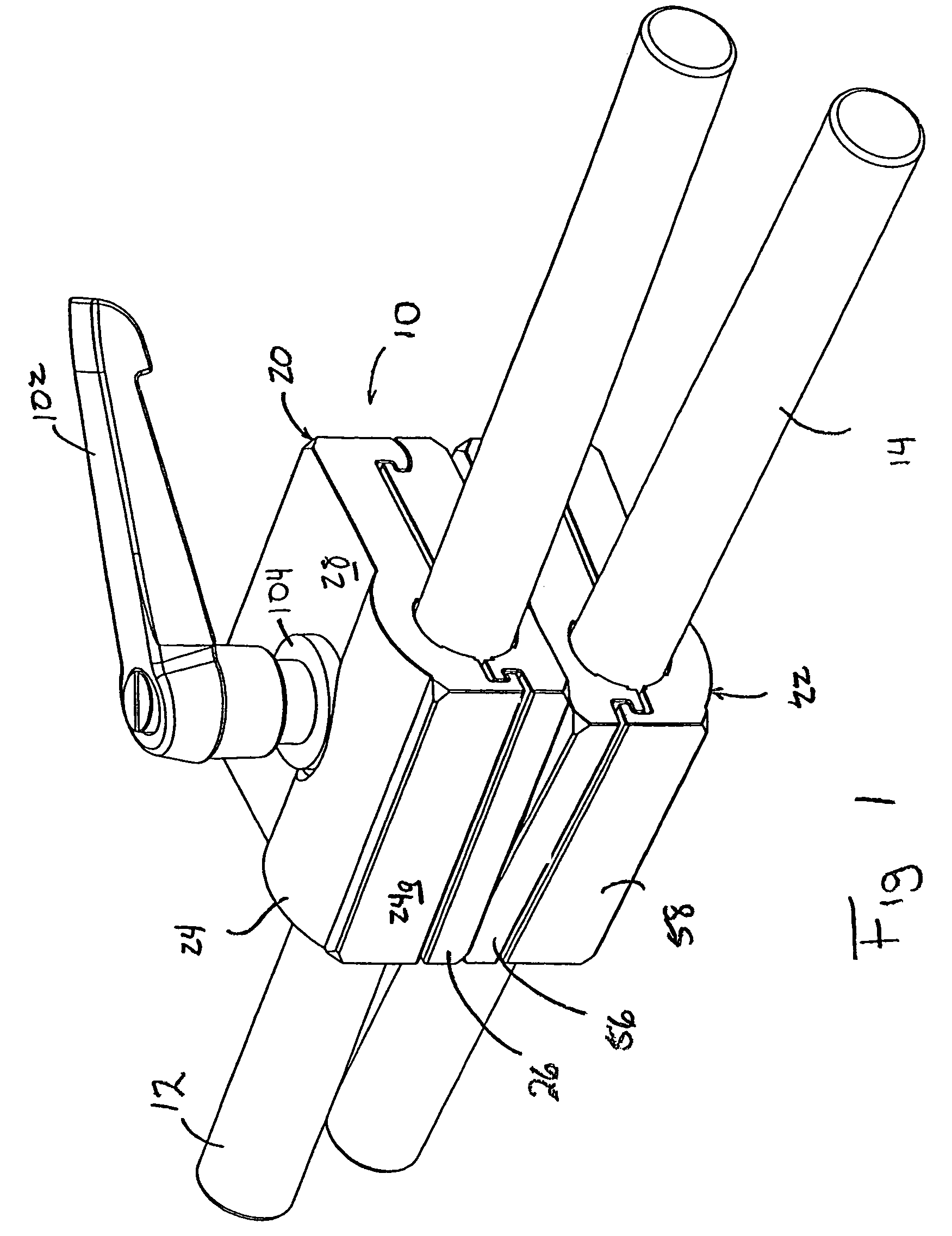
[0028]Upper and lower clamps 20 and 22, respectively, are pivotably connected to each other by a bolt 96 projecting through upper and lower clamping elements 56 and 58, respectively, of lower clamp 22 and through upper and lower clamping elements 24 and 26, respectively, of upper clamp 20. Bellville springs 98 and 100 are positioned on terminal end 96a of bolts adjacent outer surface 28 of upper clamping element 24 of upper clamp 20. In addition, handle 102 is threaded onto terminal end 96a of bolt 96. It is contemplated to provide a washer 104 on terminal end 96a of bolt 96 between handle 102 and Bellville spring 100 so as to facilitate rotation of handle 102 about the axis 106 of bolt 96.
[0029]In operation, tools 12 and 14 may be inserted into corresponding clamping cavities within upper clamps 20 and 22, respectively. As heretofore described, spring 57 acts to separate upper and lower clamping elements 24 and 26, respectively, of upper clamp 20 so as to enlarge the clamping cavity therein and facilitate the insertion of tool 12 into such clamping cavity. Similarly, spring 74 acts to separate upper and lower clamping elements 56 and 58 of lower clamp 22 so as to allow for insertion of tool 14 into the clamping cavity defined by a lower clamp 22. As described, it is contemplated that upper and lower clamps 20 and 22, respectively, of clamping mechanism 10 be pivotable about axis 106 on bolt 96 so as to allow for further alignment of tools 12 and 14, respectively. Friction disk 66 provides stability during the positioning of upper and lower clamps 20 and 22, respectively, prior to exertion of a clamping force on tools 12 and 14, as hereinafter described.
[0030]As handle 102 is threaded further onto terminal end 96a of bolt 96, handle 102 exerts a pressure on Bellville springs 98 and 100, which, in turn, exert a clamping pressure on springs 57 and 74. It is contemplated that springs 57 and 74 have different spring tensions. As a result, as handle 102 is further tightened on terminal 96a of bolt 96, the clamping pressure exerted on tools 12 and 14 within corresponding clamping cavities in upper and lower clamps 20 and 22, respectively, is progressive such that one of the tools becomes fixed within its corresponding clamping cavity prior to the other tool becoming fixed within its corresponding clamping cavity. It can be appreciated that the progressive clamping of tools 12 and 14 within the corresponding clamping cavities in upper and lower clamps 20 and 22, respectively, facilitates the positioning of tools 12 and 14 within such clamping cavities.

Problems solved by technology

However, these prior clamp mechanisms have certain disadvantages.
For example, these clamping mechanisms do not provide for progressive tensioning of each clamp holding the tools.
As a result, it is difficult to accurately position and clamp the tools for the folder gluer machine with the prior clamping mechanisms.
In addition, the clamps utilized in these prior clamping mechanisms contact the tools at a minimum number of points such that the clamping pressure exerted by the clamps is insufficient to maintain the positions of the tools supported thereby.

Method used


Image

  • Clamping mechanism for folder gluer machine
  • Clamping mechanism for folder gluer machine
  • Clamping mechanism for folder gluer machine

Examples


Embodiment Construction

[0023]Referring to FIG. 1, a clamping mechanism in accordance with the present invention is generally designated by the reference numeral 10. Clamping mechanism 10 is intended to support first and second tools 12 and 14, respectively, for use in a folder gluer machine. As is conventional, each tool 12 and 14 extends along a corresponding axis 16 and 18, respectively. By way of example, tools 12 and 14 may take the form of folding guides, finger hooks, plows, swords and / or glue applicators. However, other tools may be supported by clamping mechanism 10 without deviating from the scope of the present invention.

[0024]Referring to FIG. 2, clamping mechanism 10 includes upper clamp 20 and lower clamp 22. Upper clamp 20 includes an upper clamping element 24 and a lower clamping element 26 for receiving tool 12 therebetween. Upper clamping element 24 of upper clamp 20 includes outer surface 28 and inner surface 30. Inner surface 30 has an arcuate surface portion 32 therein that partially d...


PUM


Abstract

A clamping mechanism is provided for supporting a plurality of tools for use in a folder gluer machine. The clamping mechanism includes first and second clamps. Each clamp defines a corresponding clamping cavity for receiving a tool therein. Each clamp is movable between a release position wherein the clamping cavity has a first configuration and a clamping position wherein the clamping cavity has a second configuration. A clamping structure is operatively connected to the first and second clamps. The clamping structure sequentially moves the first and second clamps to their clamping positions.

Description

CROSS-REFERENCE TO RELATED APPLICATION[0001]This application claims the benefit of U.S. Provisional Application Ser. No. 60 / 636,217, filed Dec. 15, 2005.FIELD OF THE INVENTION[0002]This invention relates generally to folder gluer machines for making paper cartons from a traveling carton blank, and in particular, to a clamping mechanism for supporting various tools used by a folder gluer machine during a folding operation.BACKGROUND AND SUMMARY THE INVENTION[0003]As is known, a folder gluer machine is used for making paper cartons from a traveling carton blank. The carton blank is cut to an appropriate shape and scored in order to define a main carton portion and at least one flap. Thereafter, the carton blank is sent to a folder gluer machine for folding the flap to form a sidewall of the carton and to glue the sidewalls of the carton together. Typically, such paper cartons are employed in retail stores for boxing clothing or other similar items wherein a rigid carton is not require...

Claims


Application Information

Patent Timeline
Patent Type & Authority Patents(United States)
IPC IPC(8): F16L3/08B31B50/99
CPCB31B1/36F16B7/0493B31B2201/2637Y10T403/7141F16B2/10B31B50/36
Inventor OETLINGER, FRANK E.
Owner BLANKING SYST
Why Eureka
Try Eureka