Bicycle wheel and release mechanism

a technology of bicycle wheels and release mechanisms, which is applied in the direction of release mechanisms, cycle equipment, steering devices, etc., can solve the problems of increasing weight and increasing aerodynamic drag, reducing aerodynamic drag, and reducing aerodynamic drag, so as to reduce weight and reduce aerodynamic drag , the effect of increasing lateral stiffness

Inactive Publication Date: 2009-07-21
SPECIALIZED BICYCLE COMPONENTS INC
View PDF53 Cites 41 Cited by
  • Summary
  • Abstract
  • Description
  • Claims
  • Application Information

AI Technical Summary

Benefits of technology

[0010]In light of the above discussion of related art, there is a need in the art for a wheel that achieves reduced weight, reduced aerodynamic drag, and increased lateral stiffness without significant drawbacks in rideability or other desirable attributes. In various embodiments, bicycle wheels, hubs, and release mechanisms described in further detail herein meet this need. In various embodiments, a bicycle wheel has a hub with a hub flange on each end. Each flange comprises a plurality of extensions extending towards the rim from a central body of the hub. A pair of spokes desirably span from each of these hub flange extensions to the rim. The resulting reduced spoke length, combined with the rigidity from the shared two-spoke per hub flange extension structure, greatly increases lateral stiffness of the wheel as compared to a traditional spoked wheel. The flanged hub can desirably be constructed from a stiff but lightweight material such as a carbon fiber composite so that the wheel's weight is not significantly increased along with the stiffness. In various embodiments, the increased stiffness of the hub flange extension structure can be exploited to reduce aerodynamic drag. For example, in certain embodiments, the number of spokes can be reduced. In other embodiments, the distance across the hub between ends of the spokes can be reduced to reduce the frontal area of the wheel. Therefore, bicycle wheels overcoming the shortcomings of the prior art and having increased stiffness, reduced weight, and reduced aerodynamic drag are further disclosed herein.

Problems solved by technology

However, these proposed improvements typically result in certain drawbacks.
Conversely, with an attempted increased rigidity wheel, such as by increasing the number or size of spokes, increased weight and increased aerodynamic drag are often undesirable by-products of the increased rigidity.
Often, attempts to decrease aerodynamic drag, such as by incorporation of an aerodynamically sculpted “tall” rim, or incorporation of a single disk in the place of spokes, have undesirable side effects.
For example, while aerodynamic drag may be reduced with a tall rim or disk wheel, the rideability of these wheels suffers.
Wheels with tall rims or disk wheels are difficult for a rider to control in side winds.
They also often have a higher moment of inertia than a traditional spoked wheel, so require more energy to accelerate to a given rotational speed.
Moreover, tall-rimmed wheels are often relatively vertically stiff, and therefore transmit even small bumps and surface irregularities to the rider, resulting in a harsh ride.
However, this adjustment requires a two-handed operation on often dirty or greasy wheel components.

Method used


Image

  • Bicycle wheel and release mechanism
  • Bicycle wheel and release mechanism
  • Bicycle wheel and release mechanism

Examples


Embodiment Construction

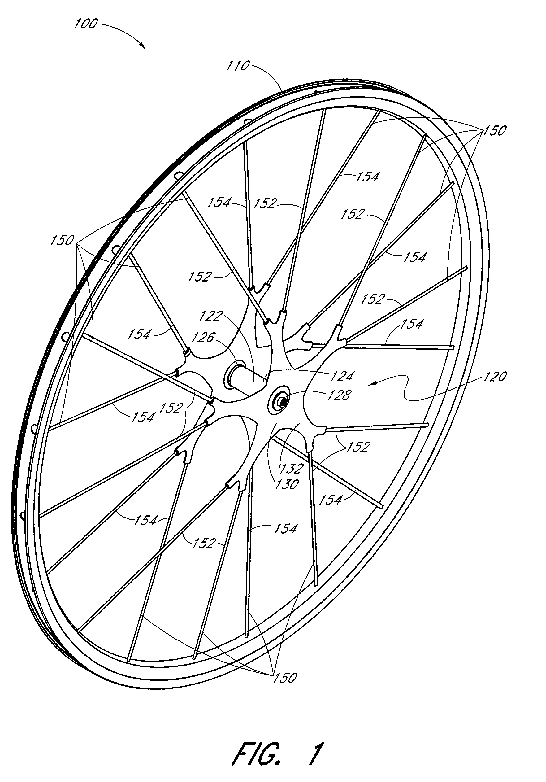
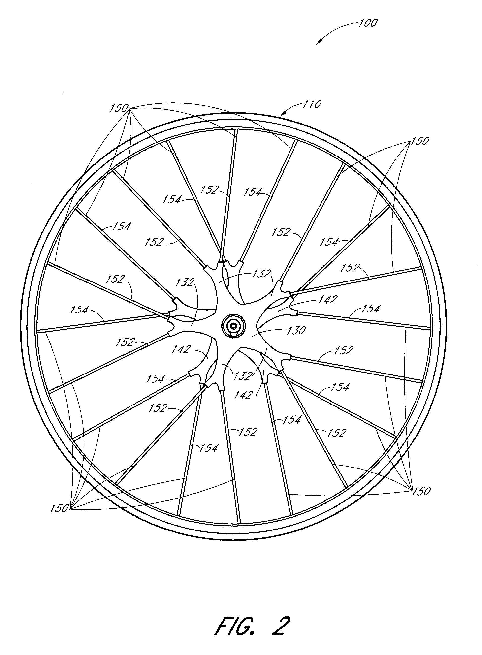
[0038]With reference to FIGS. 1-4, various embodiments of bicycle wheel 100 and hub 120 are disclosed that comprise a wheel rim 110, a hub 120 positioned at the approximate rotational center of the wheel rim 110, and a plurality of spokes 150 extending between the hub 120 and the rim 110. The hub 120 has a flanged configuration including a plurality of extensions 132, 142 from each flange 130, 140 resulting in a shorter spoke length as compared to a traditional spoked wheel 200 (FIG. 21). Advantageously, as discussed further below, the reduced spoke length increases the lateral stiffness of the wheel 100 as compared to a traditional spoked wheel 200.

[0039]FIG. 1 depicts a perspective view of a bicycle wheel 100 having a rim 110 configured to support a tire. FIG. 2 depicts a side view of the wheel of FIG. 1. Various known rim configurations may be incorporated into a wheel 100 as depicted. For example, the rim 110 desirably has a generally circular profile when viewed from the side a...


PUM


Abstract

A bicycle wheel release mechanism can be configured to fit between dropouts on a bicycle. The release mechanism can have a ramp member and a ramp interface that rotate relative to one another to define a secured position where the wheel is secured to a bicycle and an open position where the wheel is releasable from the bicycle. The ramp member can be keyed to the bicycle such that the release mechanism can be operated or adjusted via single-handed operation. The ramp member can be configured with a variable angle ramp to facilitate rapid application for initial rotation of the mechanism followed by slower application as clamping forces increase when the release mechanism approaches the secured position.

Description

CROSS-REFERENCE TO RELATED APPLICATIONS[0001]This application claims the benefit of U.S. Provisional Patent Application No. 60 / 754,026, entitled “BICYCLE WHEEL AND HUB,” filed on Dec. 22, 2005.[0002]Also, this application hereby incorporates by reference the above-identified provisional application, in its entirety.BACKGROUND OF THE INVENTION[0003]1. Field of the Invention[0004]This application relates generally to a bicycle wheel and hub and, more specifically, to a release mechanism for a bicycle wheel.[0005]2. Description of the Related Art[0006]Bicycle wheels have long included a wheel rim connected to a generally cylindrical hub by multiple spokes extending radially outward from the hub. A traditional spoked bicycle wheel is illustrated in FIG. 21, and has a rim 210, a hub 220, and a plurality of spokes 250 extending therebetween. Various wheel configurations have been attempted to achieve desirable wheel attributes of reduced weight, reduced aerodynamic drag, or increased late...

Claims


Application Information

Patent Timeline
Patent Type & Authority Patents(United States)
IPC IPC(8): B60B35/00
CPCB60B1/0223B60B1/041B60B27/026B62K25/02B60B1/042B62K2206/00
Inventor D'ALUISIO, CHRIS
Owner SPECIALIZED BICYCLE COMPONENTS INC
Why Eureka
Try Eureka