Milling head

a milling head and head technology, applied in the field of milling heads, can solve the problems of obstructing the operation of the milling head, single spraying direction of the inner pipe mounted in the body, and inability to adjust or change the spraying direction of the inner pip

Inactive Publication Date: 2009-07-21
CHEN CHIN CHIU
View PDF13 Cites 44 Cited by
  • Summary
  • Abstract
  • Description
  • Claims
  • Application Information

AI Technical Summary

Benefits of technology

[0007]The main objective of the present invention is to provide a milling head, which allows location of a coolant sprayed from the milling head to be selected conveniently.

Problems solved by technology

Although, the conventional milling head can provide a cooling effect to the milling tool by the coil pipe or the inner pipe, the coil pipe is mounted on the holding device and this obstructs operation of using the milling head.
In addition, the inner pipe mounted in the body only has a single spraying direction that cannot be adjusted or changed.

Method used


Image

  • Milling head
  • Milling head
  • Milling head

Examples


Embodiment Construction

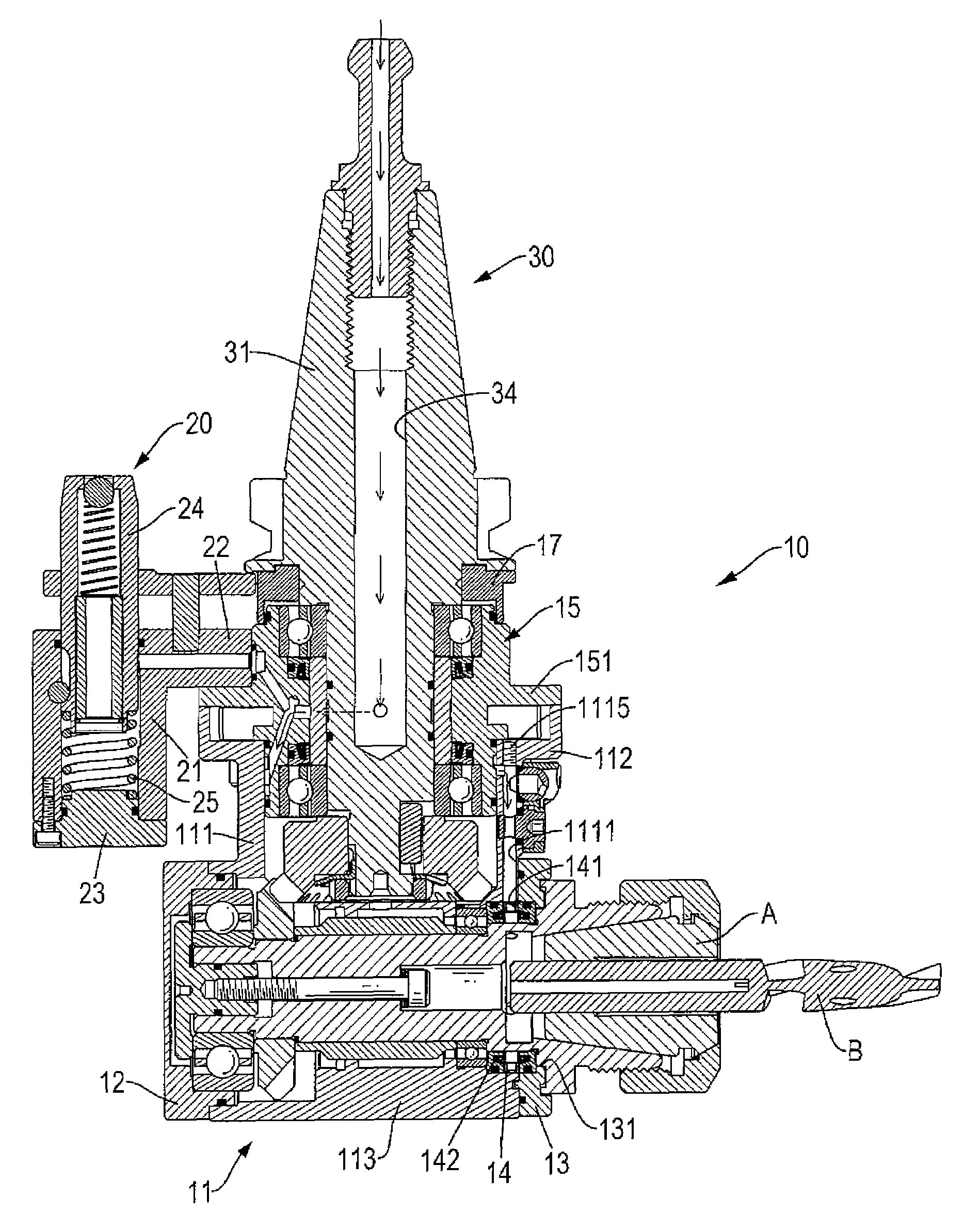
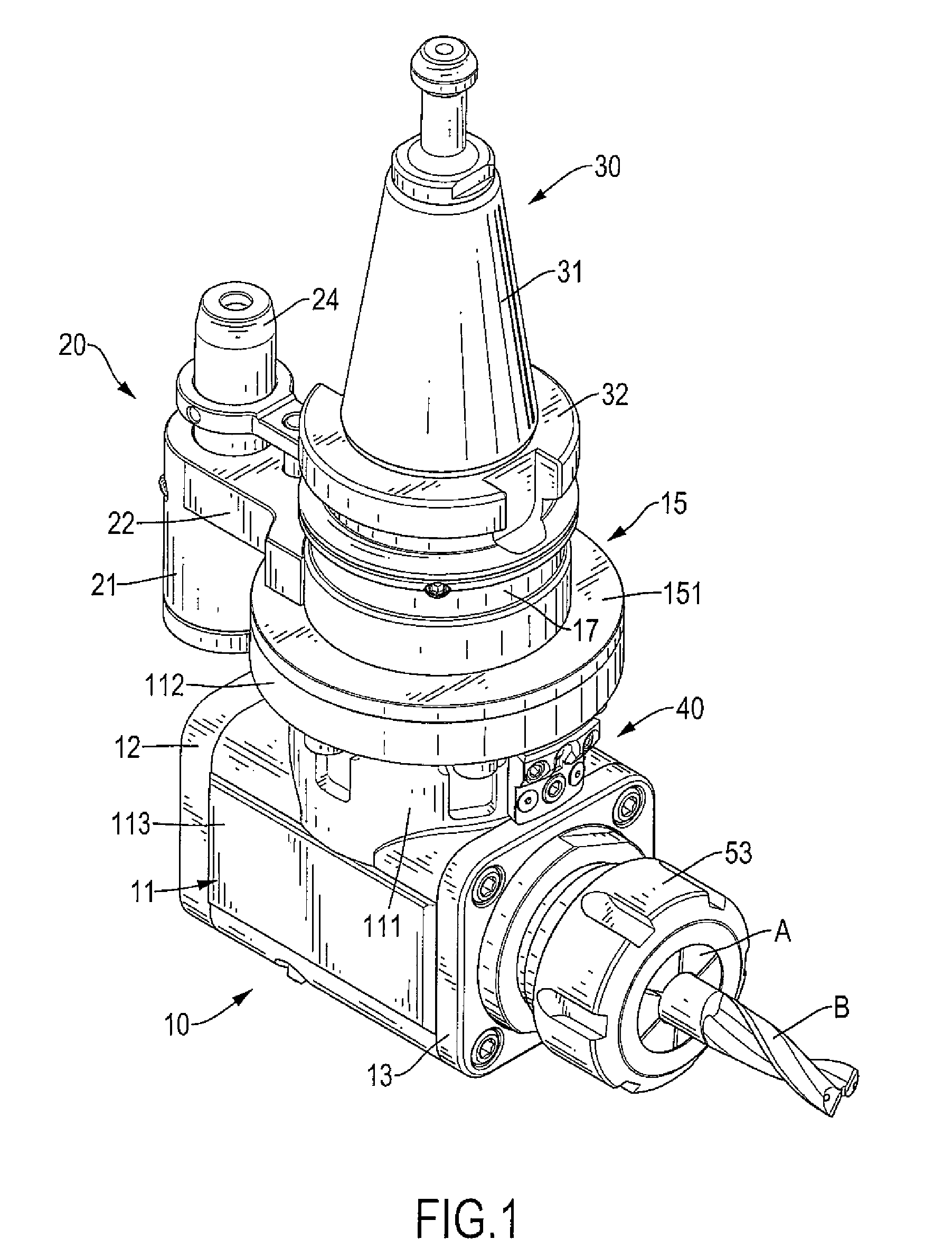
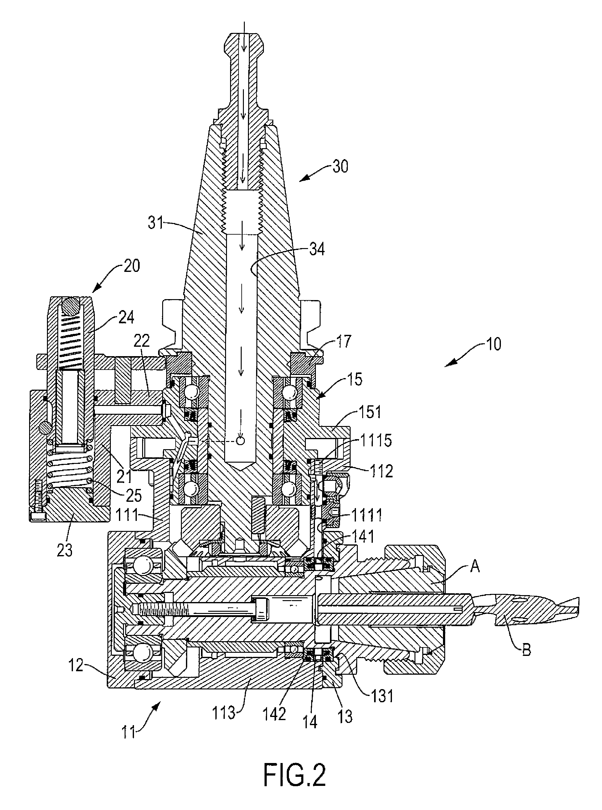
[0019]With reference to FIGS. 1 to 9, a milling head in accordance with the present invention comprises a body (10), a holding device (20), a driving axle (30), a spraying device (40) and a tool adaptor (50).

[0020]The body (10) is securely mounted on a milling machine and has a base (11), a rear cover (12), a front cover (13), a front liner ring (14), a bearing seat (15), a middle liner ring (16) and an upper cover (17).

[0021]The base (11) is securely mounted on a top of the milling machine and has a top side, a mounting segment (111), a disk segment (112) and an interconnecting segment (113).

[0022]The mounting segment (111) is tubular, is formed on the top side of the base (11) and has a top, a bottom, a front side, a flow passage (1111), an upper hole (1112), a lower hole (1113), an inlet hole (1114) and a sealing bolt (1115).

[0023]The flow passage (1111) is vertically formed in the mounting segment (111) near the front side and has an upper end, a lower end and an inner side. The...


PUM

PropertyMeasurementUnit
angleaaaaaaaaaa
structureaaaaaaaaaa
shapeaaaaaaaaaa

Abstract

A milling head has a body, a holding device, a driving axle, a spraying device and a tool adaptor. The body has a base, a rear cover, a front cover, a bearing seat and a middle liner ring. The holding device is connected to the body and has a linking arm, a mounting jacket, a bottom cap, a positioning shaft and a locating spring. The driving axle is rotatably mounted in the body and has a transmission shaft and a driving bevel gear. The spraying device is mounted on the base and has a mounting cover and an spraying ball. The tool adaptor is rotatably mounted in the base below the spraying device and has a transmitting bevel gear, a holding head and a connecting segment.

Description

BACKGROUND OF THE INVENTION[0001]1. Field of the Invention[0002]The present invention relates to a milling head, and more particularly to a milling head, which allows a location of coolant sprayed from the milling head to be selected conveniently.[0003]2. Description of Related Art[0004]A conventional milling head is mounted on a milling machine and has a body, a holding device, a driving axle, a tool adaptor and a spraying device. The body of the conventional milling head is mounted on a top of the milling machine and has a sidewall, a top side and a bottom side. The holding device is detachably mounted on the sidewall, is attached to the milling machine to hold the body with the milling machine and has a bottom. The driving axle is rotatably and vertically mounted on the top side of the body and has a lower end. The tool adaptor is mounted on the bottom side of the body, is connected to the lower end of the driving axle and has an outer end to connect a milling tool so the tool ad...

Claims


Application Information

Patent Timeline
Patent Type & Authority Patents(United States)
IPC IPC(8): B23C1/00B23Q11/10
CPCB23Q5/045B23Q11/10B23Q11/1015Y10T408/65Y10T409/304032Y10T408/455Y10T409/308456Y10T408/458Y10T408/46Y10T409/309296B23Q2220/008B23Q11/1023
Inventor CHEN, CHIN-CHIU
Owner CHEN CHIN CHIU
Why Eureka
Try Eureka