Low extraction force connector interface

a technology of low extraction force and connector interface, which is applied in the direction of coupling device connection, electrical discharge lamp, coupling device details, etc., can solve the problems of all blind mate connectors being dislodged from the device under test, and exacerbate undesirable situations, etc., and achieve the effect of low extraction for

Active Publication Date: 2009-07-21
CORNING OPTICAL COMM LLC
View PDF10 Cites 60 Cited by
  • Summary
  • Abstract
  • Description
  • Claims
  • Application Information

AI Technical Summary

Problems solved by technology

In some situations, all of the blind mate connectors could become dislodged from the device under test.
This undesirable situation can be exacerbated during rapid testing or automated testing.
Increasing the diameter of the smooth bore of the male connector interface to create less spring finger deflection and therefore less force and less friction when the connectors are mated and unmated does not entirely address this issue, because sufficient electrical connection must also be maintained between the interfaces during testing.

Method used


Image

  • Low extraction force connector interface
  • Low extraction force connector interface
  • Low extraction force connector interface

Examples


Embodiment Construction

[0018]Reference will now be made in detail to the present preferred embodiment(s) of the invention, examples of which are illustrated in the accompanying drawings. Whenever possible, the same reference numerals will be used throughout the drawings to refer to the same or like parts.

[0019]FIG. 5 illustrates one preferred embodiment of a male connector interface 80 of the present invention which, in the present example, forms part of a connector 90 which also has a female interface 92 opposite to the male interface. FIG. 6 illustrates a preferred embodiment of a male connector interface 100 of the present invention in mating engagement with a female connector interface.

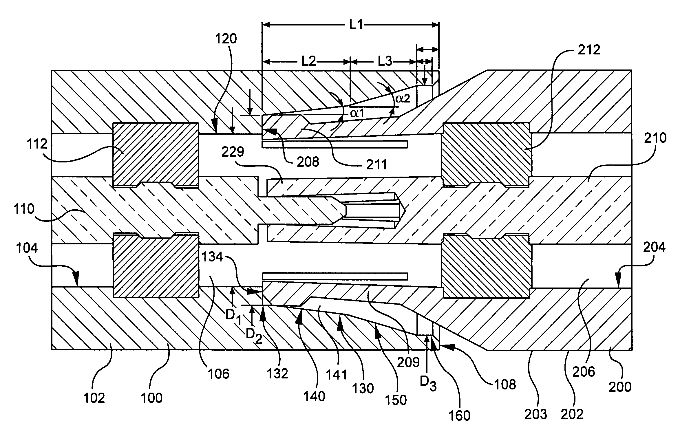
[0020]Referring to FIG. 6, the male connector interface 100 comprises a tubular housing 102 comprising an inner surface 104 that defines a longitudinal bore 106 along a longitudinal axis of the housing 102. In this embodiment, the bore 106 is a through-bore, although in other embodiments the bore may not pass all the wa...


PUM


Abstract

A male connector interface which requires a low extraction force to remove the male interface from a mating female connector interface. The male connector interface has a tubular housing with an inner surface with a first inner diameter region having an inner diameter and an increased inner diameter region having a first end disposed directly adjacent the first inner diameter region and extending to the distal end of the housing for an axial length, wherein the first inner diameter region and the first end of the increased inner diameter region define a shoulder facing the distal end of the housing, and the increased inner diameter region has a first tapered portion disposed at the first end and increasing in diameter toward the distal end, the first tapered portion defining a first frustoconical portion of the longitudinal bore.

Description

CROSS-REFERENCE TO RELATED APPLICATIONS[0001]This application claims the benefit of priority under 35 U.S.C. § 119(e) of U.S. Provisional Application Ser. No. 60 / 696,004 filed on Jul. 1, 2005, the content of which is relied upon and incorporated herein by reference in its entirety.BACKGROUND OF THE INVENTION[0002]1. Field of the Invention[0003]The present invention relates to push-on Radio Frequency (RF) coaxial connectors, and more particularly to a male RF coaxial push-on connector used for mating with female RF coaxial push-on connectors.[0004]2. Technical Background[0005]Coaxial cable and coaxial cable connectors are often used for transmitting radio-frequency (RF) signals. Examples of standard RF push-on connector interfaces can be found in MIL-STD-348 under SMP and SMPM series interfaces. Typically, male and female push-on connector interfaces are constructed to matingly engage a male and a female with a secure physical connection and a reliable electrical connection.[0006]As ...

Claims


Application Information

Patent Timeline
Patent Type & Authority Patents(United States)
IPC IPC(8): H01R9/05
CPCH01R13/6271H01R2201/20
Inventor STEIN, CASEY ROY
Owner CORNING OPTICAL COMM LLC
Why Eureka
Try Eureka