Screw threaded joint for continuous-profile tubes

a technology of continuous-profile tubes and threaded joints, which is applied in the direction of screw-type threaded joints, hose connections, mechanical equipment, etc., can solve the problems of high cost, high amount of material required for these coatings, and high drilling cost, so as to reduce production costs, facilitate installation, and high strength and tightness in situ

Inactive Publication Date: 2006-03-21
DALMINE SPA
View PDF18 Cites 30 Cited by
  • Summary
  • Abstract
  • Description
  • Claims
  • Application Information

AI Technical Summary

Benefits of technology

[0019]A particular purpose of the present invention is to provide an integral joint with a diametral dimension not greater than the diametral dimension of the tube throughout its length, which has a reduced production cost, at the same time guaranteeing high values of strength and tightness in situ.
[0020]A further purpose of the present invention is to provide a shape that facilitates installation.
[0022]Thanks to this embodiment, the joint enables facilitated installation of the tubular string, with reduced risks of seizing of the thread and of the seal, at the same time guaranteeing an optimal strength and tightness of the string at the joints.

Problems solved by technology

A disadvantageous consequence of this is that the cost of drilling is high, and the amount of material required for these coatings is also high, with consequent high costs.
Reducing to a minimum the causes of failure of joints is of fundamental importance because the failure of the tubes, above all after they have been set in operation underground, and hence in a situation where it is practically impossible for operators to intervene directly on the joint in the event of a failure in the latter, may have extremely serious economic consequences for the extraction plant and may cause considerable damage to the environment, particularly in the case where the oil or gas reservoir contain aggressive elements.
The structural problems and the problems of tightness are frequently aggravated by the temperature of the fluids, their capacity for causing corrosion, and the environmental conditions existing in the areas of extraction.
This joint is very efficient, but has a structure that is particularly complex to make and that involves high production costs.
This joint can achieve high values of efficiency, but does not have a shoulder designed to protect the joint from possible excess screwing torque, and hence from excessive stresses that would impair its functionality, and it is not provided with a metal seal.

Method used


Image

  • Screw threaded joint for continuous-profile tubes
  • Screw threaded joint for continuous-profile tubes

Examples


Embodiment Construction

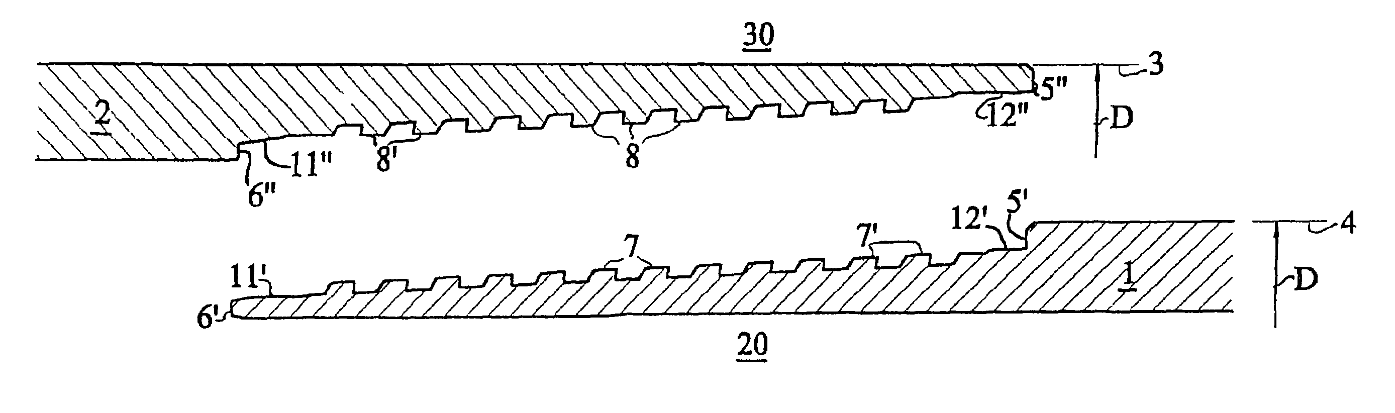
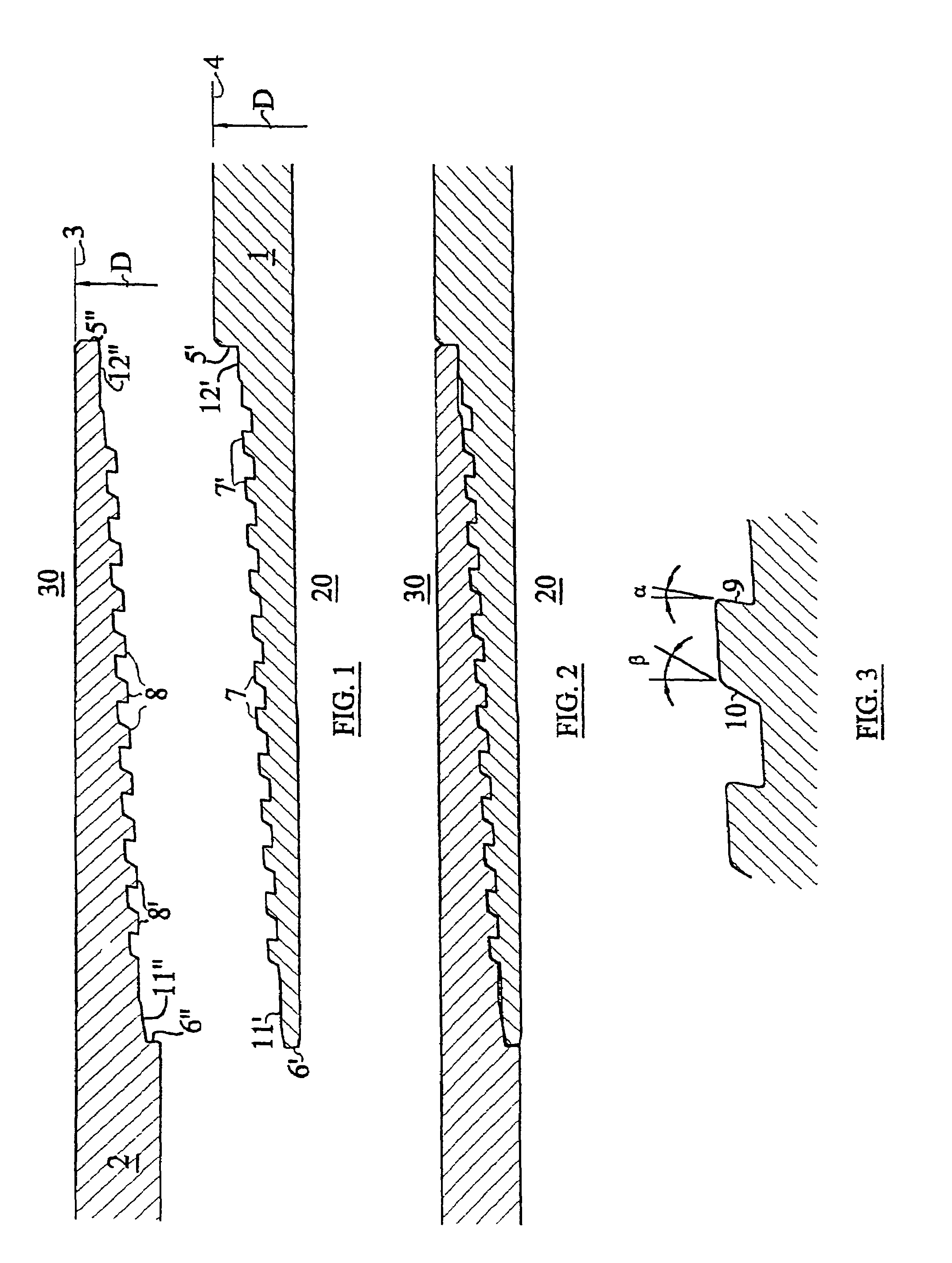
[0029]With reference to the above figures, the joint according to the invention comprises two members, or segments of tube, namely, the male part 1 and the female part 2. The joint defines an internal part 20, in which the fluid flows, for example natural gas or oil or other similar fluid, and an external part 30, which may also be filled with gases or liquids of various nature, which are also generally under pressure. The external diameter 3 of dimension D of the tube 2 in the region of the joint is equal to the external diameter of the tube itself in the part distant from the joint, minus the tolerances of fabrication of the tube. Also the tube 1, which has a male thread, has an external diameter 4 of a constant dimension D throughout its length, except for the threaded region itself.

[0030]The female member 2 of the joint has an internal thread 8 with a conical generatrix. The thread has a conicity with values of between 6.25% and 12.5%. The range indicated above is optimal becaus...


PUM


Abstract

A flush-type integral threaded joint with truncated-cone threads, with two scaling surfaces 11′, 12′, 11″, 12″) set at the end of the threaded portions (7, 8), and with two annular scaling shoulders (5′, 6′, 5″, 6″). The two threaded portions (7, 8) of the male element (1) and female element (2), respectively, have the same value of conicity, and the two sealing surfaces (11′, 12′, 11″, 12″) are, in one case, conical or cylindrical, and in the other spherical. The threaded portion of each male and female element may have an end area with a thread that is not perfect.

Description

FIELD OF INVENTION[0001]The present invention relates to an integral threaded joint with zero diametral encumbrance for tubes, in particular for tubes used in the natural-gas and oil extraction industry. The said tubes may be used both as tubing for pumping gas, oil or liquefiable hydrocarbons, and as casings for the boreholes.STATE OF THE ART[0002]In the natural-gas and oil extraction industry, when drilling oil or gas wells, tubings or casings having a pre-defined length are used, which must be joined together at their ends to form strings, in order to be able to reach the very large depths at which reservoirs of oil, gas, and liquefiable hydrocarbons are located.[0003]The most commonly used drilling technique is that of drilling wells that start from the surface of the ground or of the sea until the oil field or gas reservoir is reached. The depth of these shafts can attain several thousands of metres. During drilling, the boreholes are lined with metal casings throughout their l...

Claims


Application Information

Patent Timeline
Patent Type & Authority Patents(United States)
IPC IPC(8): F16L15/00E21B17/042F16L15/04
CPCF16L15/004F16L15/00E21B17/042
Inventor DELLA PINA, GIUSEPPEROTINI, GIUSEPPESIGNORELLI, ANGELO
Owner DALMINE SPA
Why Eureka
Try Eureka