Planetary grinder

a planetary grinder and planetary technology, applied in the direction of grinding heads, gearing, ways, etc., can solve the problems of reducing the life of the machine, adding design complications, and complicated and difficult maintenance mechanisms, and achieve the effect of convenient control by the user

Active Publication Date: 2009-07-21
NAT FLOORING EQUIP INC
View PDF21 Cites 42 Cited by
  • Summary
  • Abstract
  • Description
  • Claims
  • Application Information

AI Technical Summary

Benefits of technology

[0008]The planetary grinder has a top cover plate for supporting a motor and a transmission on its top surface, for easy access, for maintenance and repair and to keep the motor and transmission free from dust and debris resulting from the floor screeding process. The planetary grinder has a rotating planetary disk driven from the transmission's output shaft under the cover plate for supporting a plurality of rotating screeding disks. The driving mechanism for the screeding disks is sandwiched between the top cover plate and the planetary disk to protect the bearings and belts therebetween from dust and debris. The bearings for the transmission shaft and the screeding disks are sealed to further protect the parts from excess wear due to dust and debris. The top cover plate has a stationary gear attached for engaging a single toothed belt to drive the screeding disks. The belt engages the stationary gear such that, as the planetary disk rotates, the belt turns the pulleys on the screeding disk shafts to rotate the screeding disks at a speed in proportion to the rotation speed of the planetary disk. The screeding disks can be rotated in the opposite direction from the rotation of the planetary disk to counter the torque created thereby and make the planetary grinder easier to control by the user.
[0009]The planetary disk assembly is easy to remove from the transmission's output shaft to expose all the moving parts in the mechanism for cleaning, maintenance and repair or replacement of the parts. The design is simple to repair, having only one belt which drives all the screeding disks.
[0012]It is an object of the invention to provide an easy to maintain and easy to repair planetary grinder.
[0015]It is an object of the invention to provide sealed bearings on all the shafts to protect them from dust and debris.
[0016]It is an object of the invention to have the drive mechanism sandwiched between a top cover plate and the planetary disk to protect the drive mechanisms from dust and debris.

Problems solved by technology

Presently available disk floor abrading machines have separate means for rotating the planet disk and the screeding disks mounted thereon which requires a complicated and difficult to maintain mechanism for providing power to the screeding disks and the planetary disk.
Other designs have counter-rotating screeding disks which add complications to the design.
Some disk floor abrading machines expose their working mechanisms to dust, debris or abraded particles which reduce the life of the machine due to extra wear on the parts.
Other machines have hard to reach parts for making adjustments or repairs.

Method used


Image

  • Planetary grinder
  • Planetary grinder
  • Planetary grinder

Examples


Embodiment Construction

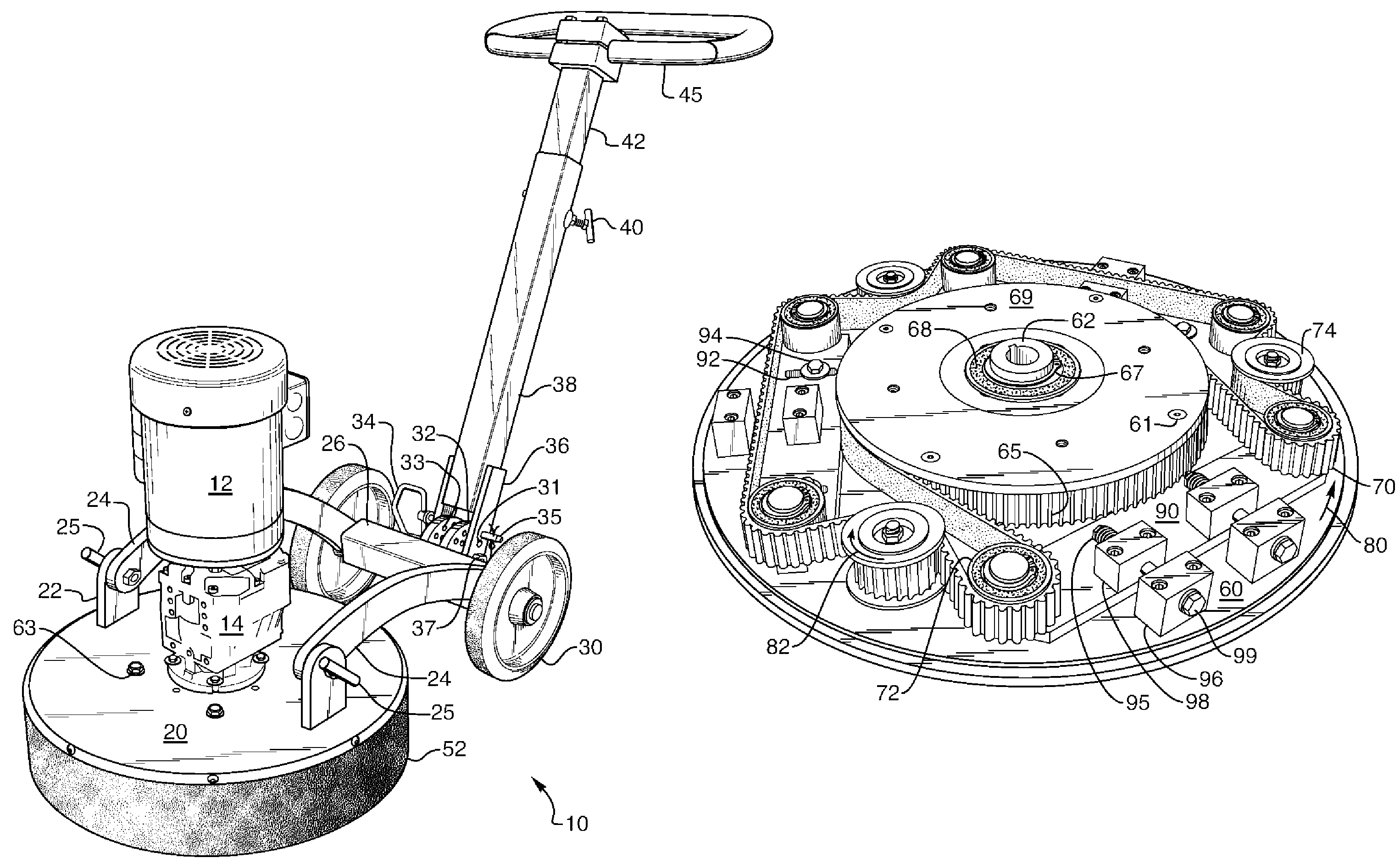
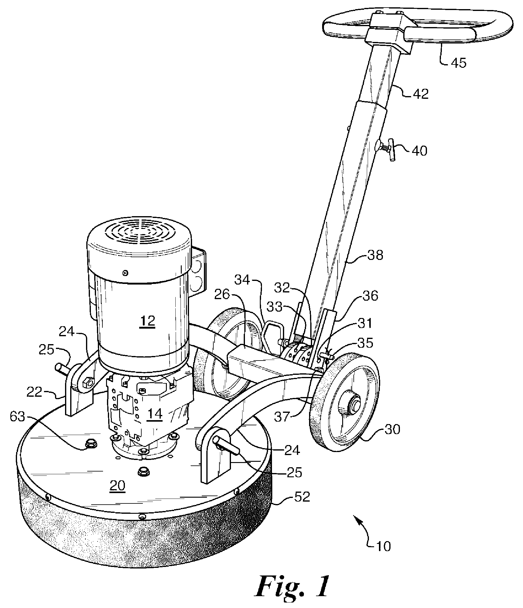
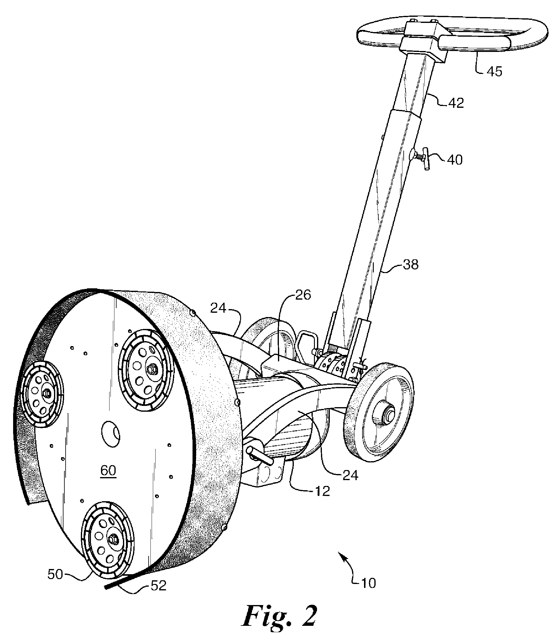
[0026]The planetary grinder 10 is shown generally in FIG. 1. It has a motor 12 which is preferably an electric motor and a transmission 14 attached to the motor 12. Although an electric motor is preferred, any kind of motor or engine for providing power can be used. The transmission 14 is attached to the top of a housing 20. Wheel mounts 22 are attached to the top of the housing 20 on each side of the transmission 14 and have arms 24 pivotally attached to the wheel mounts 22. T-bolts 25 are used to secure, either locked down or pivotally, the housing 20 in place relative to arms 24 to position the plane of the housing top 20 parallel to the floor to be worked on or perpendicular to the floor for maintenance of the screeding disks 50. The length of the arms 24 are preferably longer than the height of the motor 12 and the transmission 14 such that when the housing 20 is tilted perpendicular to the floor, the top of the motor 12 will clear the axle housing 26 at the end of the arms 24....


PUM


Abstract

A planetary grinding machine having a simple design with a minimal number of parts, which are all easily accessible for maintenance and repair is disclosed. The machine has a rotating planetary disk with rotating screeding disks attached. The planetary disk is driven by a shaft extending through a top housing cover plate, which supports a transmission driven by a motor. As the planetary disk rotates, a single belt engages a stationary gear on the cover plate and pulleys on screeding disk shafts to turn the screeding disks as the planetary disk is turned. The belts and pulleys for the drive mechanism are sandwiched between the planetary disk and the top cover to protect the mechanisms from dust and debris. The bearings are sealed to prevent dust and debris from entering and oil from escaping. The bearings, being on the inside of the planetary disk, keep oil from landing on the floor.

Description

BACKGROUND OF THE INVENTION[0001]1. Field of the Invention[0002]This invention relates to a planetary grinder for abrading floor surfaces with a rotating circular planar surface tool and more particularly to the planetary drive mechanism of the planetary grinder.[0003]2. Description of the Related Art[0004]Presently available disk floor abrading machines have separate means for rotating the planet disk and the screeding disks mounted thereon which requires a complicated and difficult to maintain mechanism for providing power to the screeding disks and the planetary disk.[0005]In some designs there are multiple gears or multiple belts needed to drive the planet disk and the screeding disks. Other designs have counter-rotating screeding disks which add complications to the design.[0006]Some disk floor abrading machines expose their working mechanisms to dust, debris or abraded particles which reduce the life of the machine due to extra wear on the parts. Other machines have hard to re...

Claims


Application Information

Patent Timeline
Patent Type & Authority Patents(United States)
IPC IPC(8): B24B23/00
CPCB24B7/186B24B41/047F16H7/023B24B55/00B24B47/10
Inventor ANDERSON, MARTIN L.
Owner NAT FLOORING EQUIP INC
Why Eureka
Try Eureka