Supercharge Your Innovation With Domain-Expert AI Agents!

Toroidal-type continuously variable transmission

a transmission device and continuously variable technology, applied in the direction of gearing details, mechanical equipment, gearing, etc., can solve the problems of inability to fully remove foreign substances made of metal in oil of oil pans, and sometimes inability to remove foreign substances fully by line filters,

Inactive Publication Date: 2009-07-21
NSK LTD
View PDF24 Cites 7 Cited by
  • Summary
  • Abstract
  • Description
  • Claims
  • Application Information

AI Technical Summary

Benefits of technology

The present invention provides a toroidal-type continuously variable transmission that can remove foreign substances such as metal particles and oil drops before they are jetted out onto the traction surfaces of the input and output disks. This is achieved by using a magnet member in the oil passage of the transmission. Additionally, the invention includes a cover member for covering the lower portions of the input and output disks, and a support post for supporting the associated links. The technical effects of the invention include improved performance and durability of the transmission.

Problems solved by technology

However, sometimes, the line filter disposed on the suction side is unable to remove the foreign substances fully.
Also, foreign substances made of metal remaining in the oil of an oil pan, sometimes, cannot be removed fully by the line filter but they are jetted out onto the traction surfaces.
In these cases, there is a fear that the foreign substances can be bitten into the rolling contact points between the disks and power rollers.
And, even in case where the foreign substances are not bitten into the rolling contact points but are stored together with the lubricating oil on the lower side of the variator, there is a fear that the foreign substances in the oil (including foreign substances which have been previously present in the lubricating oil collecting in the oil collecting portion) can be caused to move violently due to the vibrations of the composing parts of the toroidal-type continuously variable transmission while it is in operation and can be bitten, together with the lubricating oil which is stored in the oil collecting portion and is scraped up by the disks, into the traction surfaces of the disks and power rollers again.
Such biting of the foreign substances reduces the lives of the input and output disks and power rollers.

Method used


Image

  • Toroidal-type continuously variable transmission
  • Toroidal-type continuously variable transmission
  • Toroidal-type continuously variable transmission

Examples


first embodiment

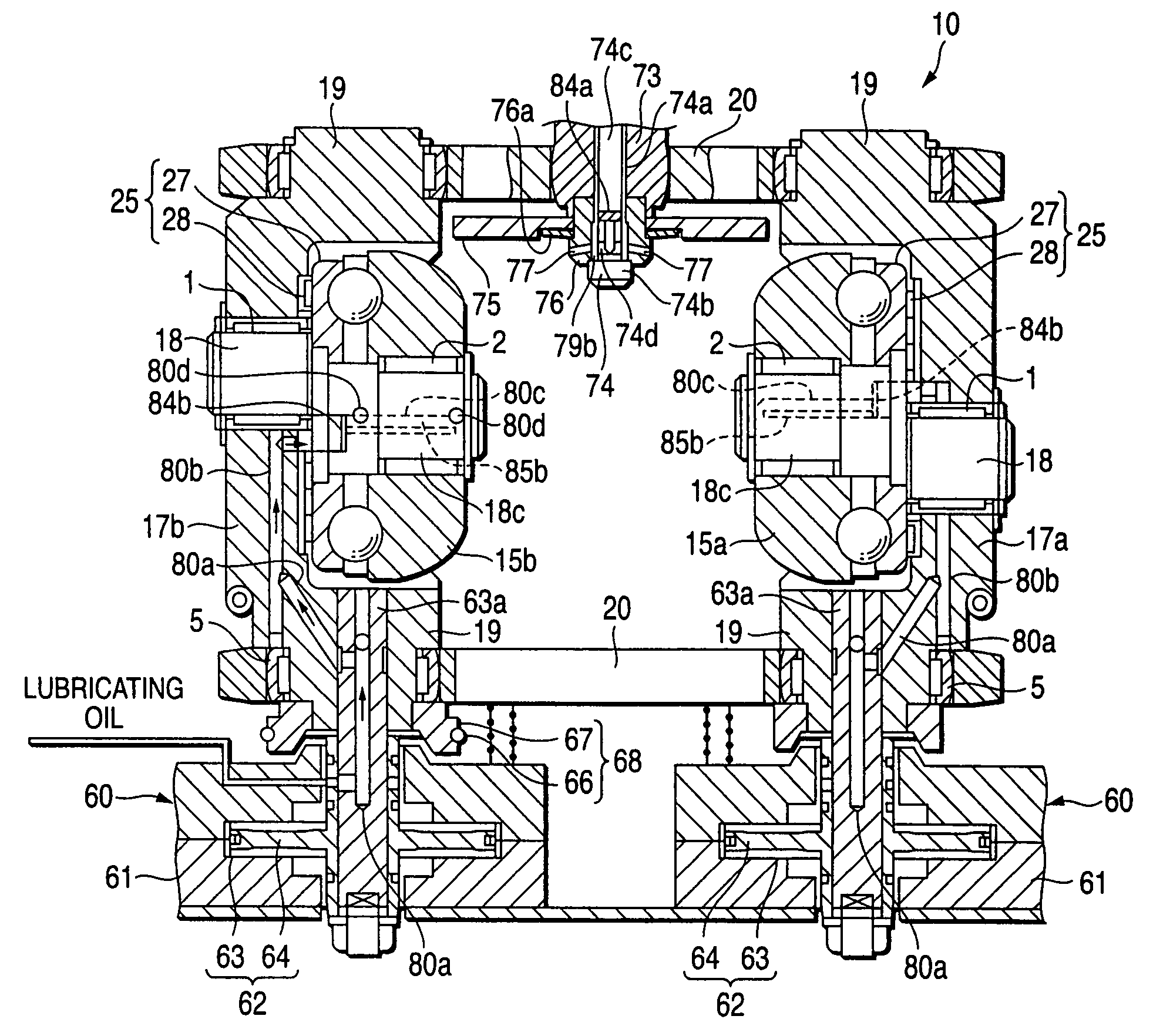
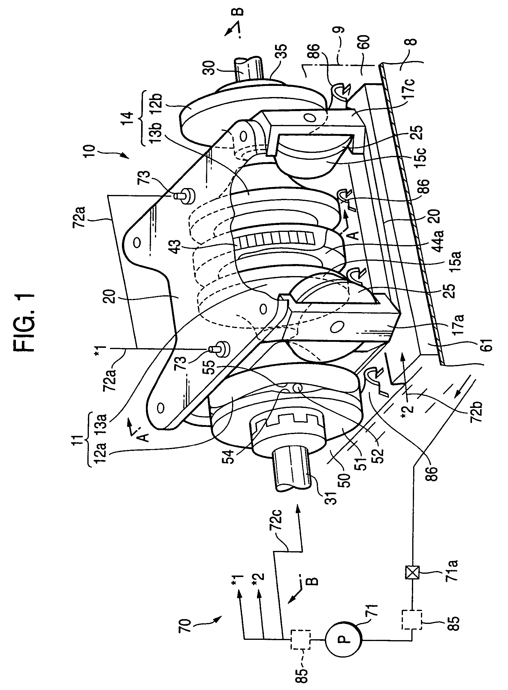
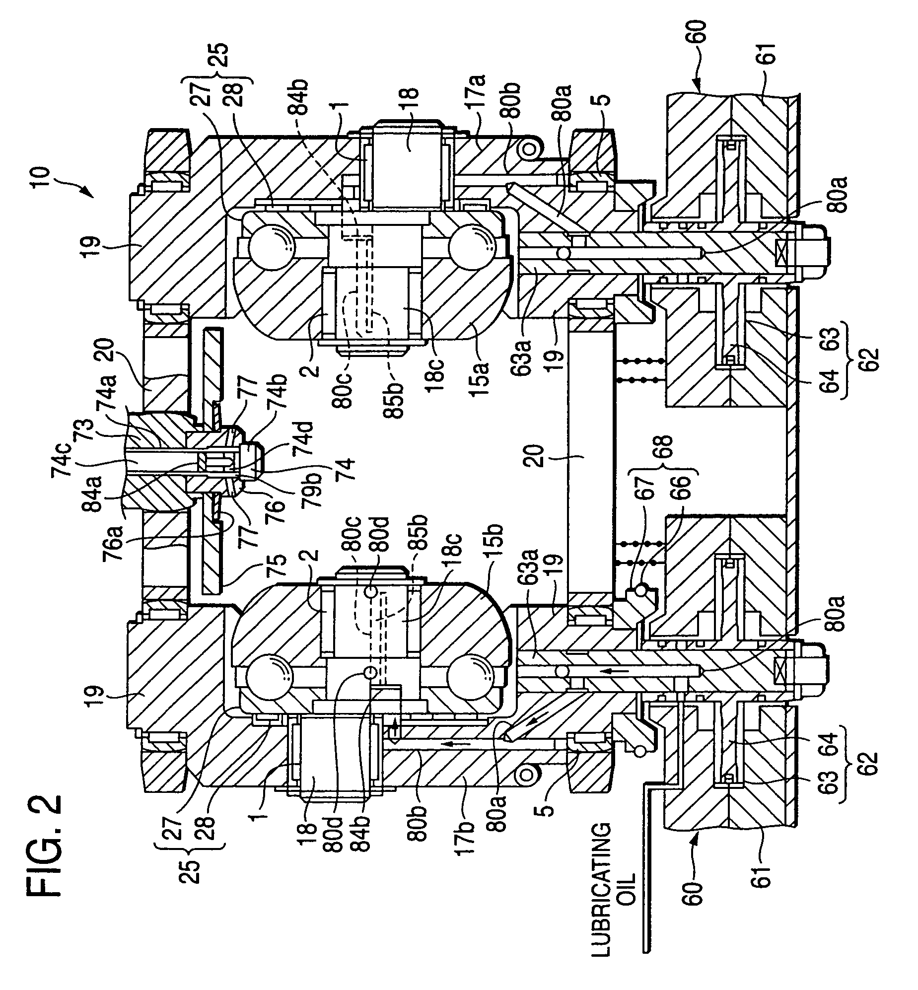
[0053]Now, description will be given below of the present invention with reference to a first embodiment shown in FIGS. 1 to 7.

[0054]FIG. 1 shows a variator 10 constituting the main part of a half-toroidal-type continuously variable transmission of a double cavity type according to the present invention, FIG. 2 shows a section view taken along the line A-A shown in FIG. 1, and FIG. 3 shows a section view taken along the line B-B shown in FIG. 1. The variator 10 is stored in a mission case (part of which is shown by a two-dot chained line in FIG. 1) with an oil pan part 8 (as a oil collecting portion collecting the lubricating oil) formed in the lowest portion thereof. The variator 10 comprises an input disk 12a and an output disk 13a constituting a first cavity 11, and an input disk 12b and an output disk 13b constituting a second cavity 14. The input disks 12a, 12b and output disks 13a, 13b respectively include first traction surfaces 12c, 12d, 13c, 13d on the inner surfaces thereo...

second embodiment

[0097]Specifically, in the second embodiment shown in FIG. 8A, on the wall surface of the hole portion 77a extending at right angles to the axial direction of the bolt member 74 connecting together the injection holes 77 of the injection head 76, there is mounted a flat-shaped first magnet member 85a so as to extend along the present wall surface.

third embodiment

[0098]In the third embodiment shown in FIG. 8B, a flat-shaped first magnet member 85a is mounted on the wall surface of the through hole having a small diameter formed just in the rear of a first mesh filter 84a.


PUM


Abstract

A toroidal-type continuously variable transmission has a pair of input and output disks each including a first traction surface, power rollers each including a second traction surface and respectively interposed between the first traction surfaces of the input and output disks, an oil passage for guiding lubricating oil to the traction surfaces of the power rollers, input disk and output disk, and a mesh filter disposed on the exit side of the associated oil passage.

Description

BACKGROUND OF THE INVENTION[0001]1. Field of the Invention[0002]The present invention relates to a toroidal-type continuously variable transmission which can be used, for example, as a transmission for a vehicle.[0003]2. Description of the Related Art[0004]As an automatic transmission for a vehicle, there is conventionally used a toroidal-type continuously variable transmission.[0005]In this type of toroidal-type continuously variable transmission, as shown in U.S. Pat. Nos. 5,099,710 or 5,286,240, there is used a structure in which a pair of input and output disks are combined together on the two sides of a set of power rollers so as to hold the power rollers. Specifically, the traction surfaces of the respective disks are formed in a convex-surface shape obtained by an arc, the center of which is the swing shaft of the power roller; and, in case where the power rollers are inclinedly rotated, the rotation radius ratio of the contact points between the power rollers and input and o...

Claims


Application Information

Patent Timeline
Patent Type & Authority Patents(United States)
IPC IPC(8): F16H15/38
CPCF16H15/38F16H57/043F16H57/049
Inventor IMANISHI, TAKASHIKIMURA, KAZUYASEKIGUCHI, SACHIKO
Owner NSK LTD
Features
  • R&D
  • Intellectual Property
  • Life Sciences
  • Materials
  • Tech Scout
  • Unparalleled Data Quality
  • Higher Quality Content
  • 60% Fewer Hallucinations
Learn More