Multi-cyclone dust separating apparatus

a multi-cyclone, dust-separating technology, applied in the field of vacuum cleaners, can solve the problems of reducing the efficiency of dust collection of multi-cyclone dust-separating apparatus, and frequent replacement of dust-bags, etc., to prevent pressure drop

Inactive Publication Date: 2009-07-21
SAMSUNG GWANGJU ELECTRONICS CO LTD
View PDF13 Cites 23 Cited by
  • Summary
  • Abstract
  • Description
  • Claims
  • Application Information

AI Technical Summary

Benefits of technology

[0015]Accordingly, it is an object of the present invention to provide a multi-cyclone dust separating apparatus that can maintain an appropriate suction force and prevent pressure drop, by restricting mixing of the air supplied to cyclones and the air discharged through discharge guide tubes.
[0016]Another object of the present invention is to provide a multi-cyclone dust separating apparatus that can prevent pressure drop by collision of the air passing through a grill member for filtering off dusts from different directions.
[0017]In order to achieve the above objects of the invention, there is provided a cyclone dust separating apparatus, including: a cyclone body having an air inflow hole through that the outside air containing impurities is sucked; and a discharge guide tube for discharging the air from the cyclone body, the discharge guide tube including a cylindrical portion, and an intercepting portion extended from the bottom end of the cylindrical portion for preventing the air supplied to the cyclone body from being directly discharged to the discharge guide tube. Therefore, the cyclone dust separating apparatus can maintain an appropriate suction force, restricting mixing of the air supplied to the cyclone body and the discharged air.
[0019]According to one aspect of the invention, there is provided a multi-cyclone dust separating apparatus, including: a primary cyclone for centrifugally separating impurities from the sucked air; a plurality of secondary cyclones for centrifugally separating impurities from the air supplied from the primary cyclone; inflow guide paths for guiding the air discharged from the primary cyclone to the plurality of secondary cyclones; and discharge guide tubes partially inserted into the secondary cyclones, for externally discharging the air of the secondary cyclones. The discharge guide tubes include cylindrical portions, and intercepting portions extended from the bottom ends of the cylindrical portions, for preventing the air supplied to the secondary cyclones from being directly discharged to the discharge guide tubes.
[0023]Preferably, in the multi-cyclone dust separating apparatus, the primary cyclone includes a cylindrical grill member installed on an air outflow hole through which the air is discharged, for preventing backflow of impurities. The grill member includes an air guide member protruded from the bottom in the height direction, for guiding the air passing through the grill member to the air outflow hole.

Problems solved by technology

The dust bag is frequently replaced and unsanitary.
However, the air supplied to the cyclone body rotates and collides with the discharge air discharged through the discharge guide tube, thereby causing a pressure drop and a reduction in the suction force.
Particularly, a multi-cyclone dust separating apparatus having a plurality of cyclones to improve the dust collecting efficiency has such problems in the secondary or tertiary cyclones composed of a plurality of small cyclones.
First, when the air discharged from the primary cyclone 30 is supplied to the secondary cyclones 40 through the inflow guide tubes 52, as indicated by arrows A, most of the air is not supplied to the lower portions of the secondary cyclones 40 but directly discharged to the discharge guide tubes 53 by the suction force of the discharge guide tubes 53. Therefore, the minute impurities that have not been filtered in the primary cyclone 30 are externally discharged through the cyclone cover 60 with the air, thereby reducing the dust collecting efficiency of the multi-cyclone dust separating apparatus 10.
If the suction force decreases, the secondary cyclones 40 cannot form a proper rotary current, thereby reducing the dust collecting efficiency.

Method used


Image

  • Multi-cyclone dust separating apparatus
  • Multi-cyclone dust separating apparatus
  • Multi-cyclone dust separating apparatus

Examples


Embodiment Construction

[0033]A multi-cyclone dust separating apparatus in accordance with the present invention will now be described in detail with reference to the accompanying drawings.

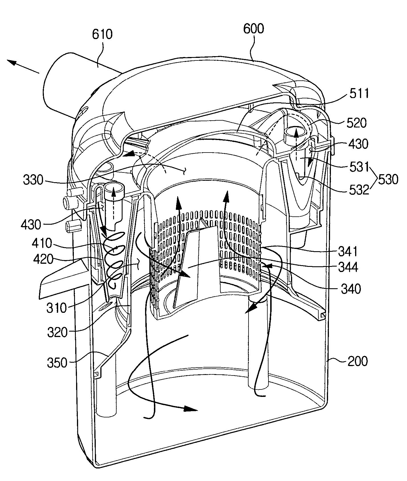
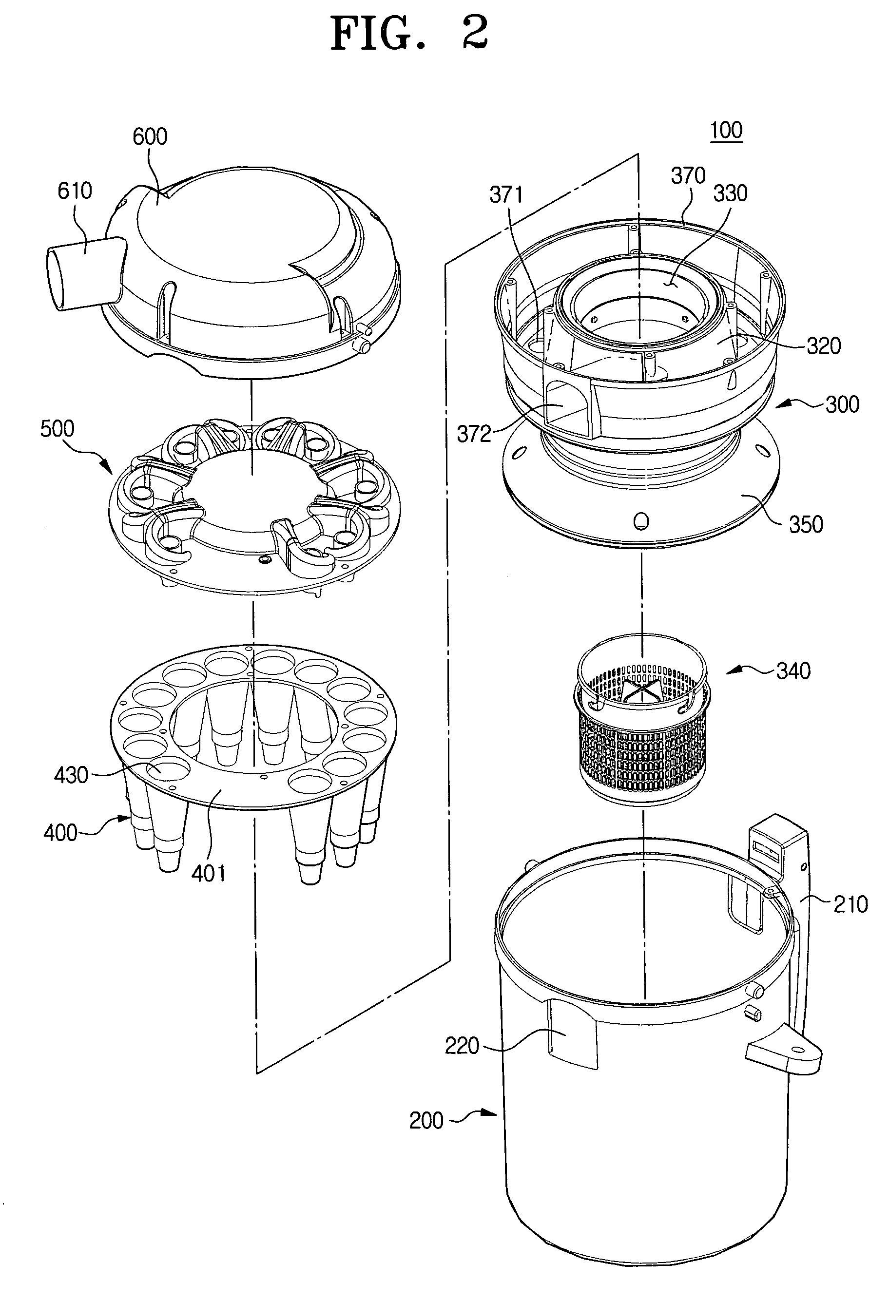
[0034]As illustrated in FIG. 2, the multi-cyclone dust separating apparatus 100 includes a dust collecting housing 200, a primary cyclone 300 installed in the dust collecting housing 200, a plurality of secondary cyclones 400 installed in the dust collecting housing 200 on the outer circumference of the primary cyclone 300 at predetermined intervals, an inflow / outflow cover 500 coupled to the upper portions of the primary and secondary cyclones 300 and 400, and a cyclone cover 600 coupled to the upper portion of the inflow / outflow cover 500.

[0035]The primary cyclone 300 primarily centrifugally separates and removes relatively large impurities of the sucked air, and the secondary cyclones 400 secondarily centrifugally separate and remove minute impurities of the air supplied from the primary cyclone 300. The dust collecti...


PUM

PropertyMeasurementUnit
lengthaaaaaaaaaa
lengthaaaaaaaaaa
lengthaaaaaaaaaa

Abstract

Disclosed is a multi-cyclone dust separating apparatus including a primary cyclone for centrifugally separating impurities from the sucked air, a plurality of secondary cyclones for centrifugally separating impurities from the air supplied from the primary cyclone, inflow guide paths for guiding the air discharged from the primary cyclone to the plurality of secondary cyclones, and discharge guide tubes partially inserted into the secondary cyclones, for externally discharging the air of the secondary cyclones. The discharge guide tubes include cylindrical portions having a predetermined height, and intercepting portions extended from the bottom ends of the cylindrical portions by a predetermined length, for preventing the air supplied to the secondary cyclones from being directly discharged to the discharge guide tubes.

Description

CROSS-REFERENCE TO RELATED APPLICATIONS[0001]This application claims benefit under 35 U.S.C. §119(a) of Korean Patent Application No. 2005-50917, filed Jun. 14, 2005 in the Korean Intellectual Property Office, the entire contents of which are incorporated herein by reference.BACKGROUND OF THE INVENTION[0002]1. Field of the Invention[0003]The present invention relates to a vacuum cleaner, and more particularly, to a multi-cyclone dust separating apparatus that can centrifugally separate impurities from the sucked air.[0004]2. Description of the Related Art[0005]In general, a vacuum cleaner includes a suction brush for sucking the air containing impurities from the bottom, a dust separating apparatus for separating the impurities from the air sucked through the suction brush, and a suction motor that generates a suction driving source. The dust separating apparatus normally uses a dust bag. The dust bag is frequently replaced and unsanitary. Accordingly, a multi-cyclone dust separatin...

Claims


Application Information

Patent Timeline
Patent Type & Authority Patents(United States)
IPC IPC(8): B01D45/12
CPCA47L9/1625A47L9/1641B04C5/24A47L9/1666B04C5/13A47L9/1658Y10S55/03A47L9/10A47L9/16
Inventor KIM, KYOUNG-WOUNG
Owner SAMSUNG GWANGJU ELECTRONICS CO LTD
Why Eureka
Try Eureka