
Generating detector efficiency estimates for a pet scanner

a technology of positron emission tomography and detector efficiency, which is applied in the direction of measuring devices, instruments, material analysis through optical means, etc., can solve the problems of poor image quality, inability to obtain detector efficiency estimates, and accordingly reduced scan results

Inactive Publication Date: 2009-07-21
HAMMERSMITH IMANET
View PDF10 Cites 0 Cited by
  • Summary
  • Abstract
  • Description
  • Claims
  • Application Information

AI Technical Summary

Benefits of technology

"The patent is about a method and computer software for generating detector efficiency estimates for a positron emission tomography (PET) scanner. This is important for detecting any deterioration in the operation of the detectors in the scanner, as poor image quality can result from deteriorated detector efficiencies. The method involves performing a blank scan and a transmission scan in the PET scanner, and using the results of these scans to estimate the detector efficiencies. This information is then used to detect and correct for attenuation in the PET images. The patent also describes an alternative PET scanner arrangement that uses a single photon source for the transmission scan, and how the detector efficiencies are estimated in this case. The technical effect of this patent is to provide a more accurate way of detecting and correcting for detector efficiency in PET scanners, which can improve the accuracy of the resulting images."

Problems solved by technology

It would be desirable to be able to ascertain detector efficiencies in order to be able to detect deterioration in the state of operation of detectors in the detector array, since upon deterioration of a detector, the scan results are accordingly reduced in accuracy, leading to poor image quality.
However, detector efficiency estimates are not obtained from these results.
In these cases, the model given by equation (1) above is no longer appropriate, as the rotation causes the direct inter-relation between detectors and entries in the sinogram bins to break down.
A problem with having to conduct a phantom scan is that the phantom must be handled by an operator to place the phantom inside the scanner and to subsequently remove the phantom.
It is both inconvenient and time-consuming, since in any event an operator needs to be available to handle the phantom at the start and end of the procedure.
It is also potentially hazardous, in terms of lifting the phantom and exposure to radioactivity.
However, detector efficiency data cannot be accurately estimated from artificial coincidence counts using known techniques, because the known measurement models do not apply.

Method used


Image

  • Generating detector efficiency estimates for a pet scanner
  • Generating detector efficiency estimates for a pet scanner
  • Generating detector efficiency estimates for a pet scanner

Examples


Embodiment Construction

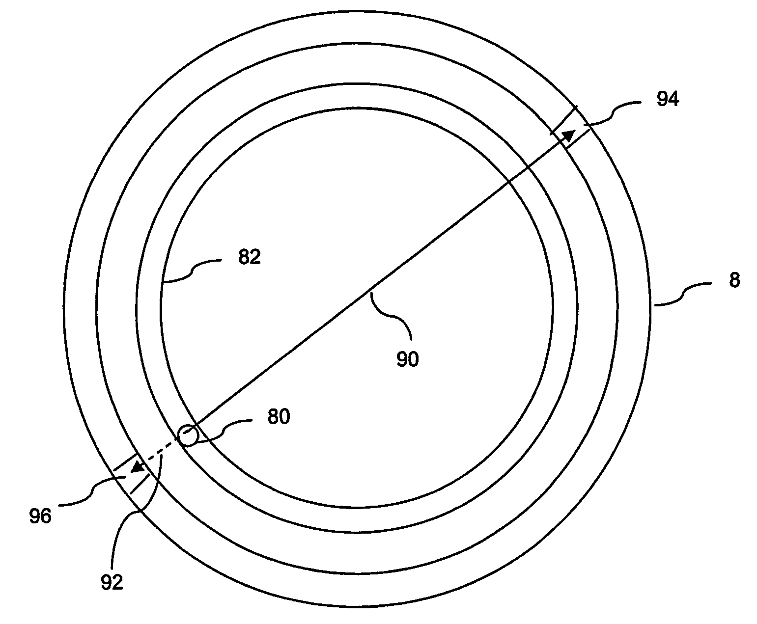
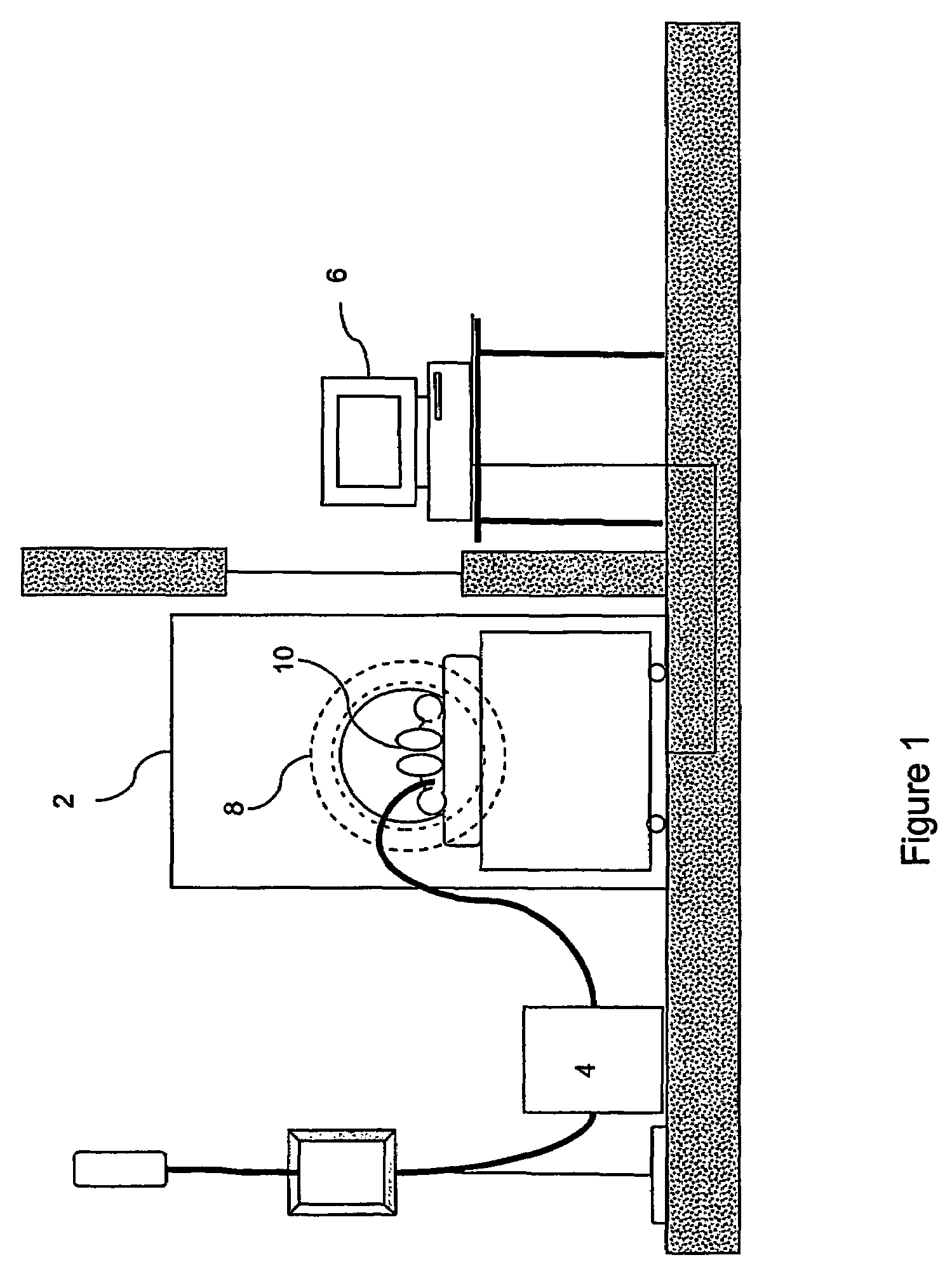
[0034]Referring now to FIG. 1, a PET scanning facility, arranged in accordance with an embodiment of the invention, is shown, which includes a PET scanner 2, a tracer generator module 4 and an operator computer terminal 6. The scanner 2 includes a detector array 8 arranged about a scanning area, in which a subject 10 is located during a transmission scan and during an emission scan.

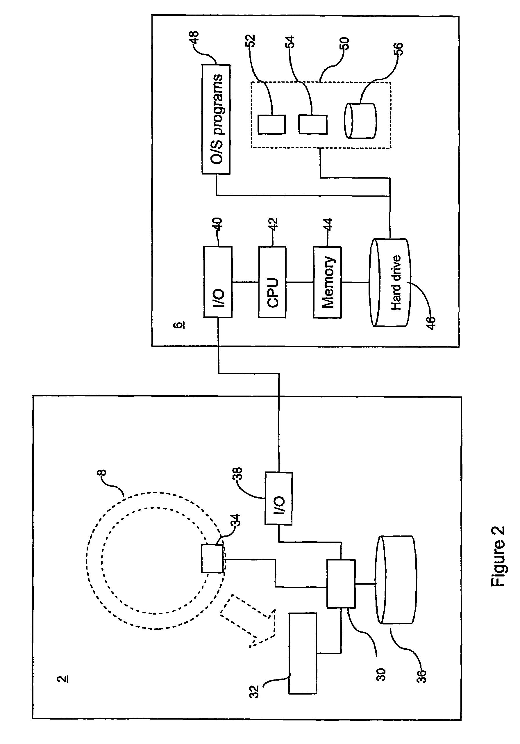
[0035]As shown in FIG. 2, the PET scanner 2 includes a control unit 30, detection data processing circuitry 32, one or more single photon source position detectors 34, a count store 36 and an Input / Output (I / O) device 38. The computer terminal 6 includes a central processing unit (CPU) 42, memory 44, hard disc drive 46 and I / O device 40, which facilitates interconnection of the computer 6 with the PET scanner 2. Operating system programs 48 are stored on the hard disc drive 46, and control, in a known manner, low level operation of the computer terminal 6. Program files and data 50 are also stored on the ...


PUM


Abstract

Detector efficiency data is generated for a positron emission tomography scanner (2) including a single photon source by conducting a blank scan acquisition procedure using the single photon source. The acquired detection count data is processed using an efficiency estimation algorithm to calculate data efficiencies of individual detectors in the detector array (8). In one embodiment, the detection count data is output as artificial coincidence count data and the efficiency estimation algorithm operates on the artificial coincidence count data. The method can be used in a non-rotating scanner or a rotating scanner.

Description

[0001]This application is a filing under 35 U.S.C. 371 of international application number PCT / GB2004 / 002340, filed Jun. 3, 2004, which claims priority to application number 0312776.8 filed Jun. 4, 2003, in Great Britain the entire disclosure of which is hereby incorporated by reference.FIELD OF THE INVENTION[0002]This invention relates to a method of, and computer software for, generating detector efficiency estimates for a positron emission tomography (PET) scanner including a detector array for generating detection data and a single photon source.BACKGROUND OF THE INVENTION[0003]There are various different types of acquisition procedure in PET, including an emission scan, a transmission scan and a blank scan.[0004]A typical emission scan begins with the injection of a solution including a tracer, which is a pharmaceutical compound including a radio-isotope with a short half-life, into the subject. The subject may be human or animal. The tracer moves to, and is typically taken up,...

Claims


Application Information

Patent Timeline
Patent Type & Authority Patents(United States)
IPC IPC(8): G01T1/164G01T1/166G01T1/29
CPCG01T1/2985
Inventor HOGG, DARRENTHIELEMANS, KRIS FILIP JOHAN JULES
Owner HAMMERSMITH IMANET
Learn More