Discharge lamp lighting circuit with frequency control in accordance with phase difference

a technology of phase difference and lighting circuit, which is applied in the direction of process and machine control, instruments, light sources, etc., can solve the problems of large switching loss, reduced power efficiency, and difficulty in setting the frequency change

Inactive Publication Date: 2009-07-21
KOITO MFG CO LTD
View PDF6 Cites 8 Cited by
  • Summary
  • Abstract
  • Description
  • Claims
  • Application Information

AI Technical Summary

Benefits of technology

[0009]Exemplary embodiments of the present invention provide a discharge lamp lighting circuit which, in a lighting control of a discharge lamp, can sufficiently maintain a lighting property correspondingly with environmental characteristics such as variations of a power source voltage and dispersions of the operating temperature, and changing characteristics of circuit components.
[0011]In the discharge lamp lighting circuit, the phase difference between the input voltage and input current that are supplied from the inverter circuit to the series resonant circuit is detected, whereby the inductive and capacitive depths of the series resonant circuit as viewed from the inverter circuit are determined, and the driving frequency of the inverter circuit is increased or decreased on the basis of the phase difference. According to such a configuration, the driving frequency of the inverter circuit can be adjusted following the resonant frequency of the series resonant circuit. Even when circuit or environmental characteristics are varied, therefore, a sufficient power can be supplied to the discharge lamp, and the lighting stability of the discharge lamp can be advantageously ensured.
[0013]In such a case, by the phase difference detecting portion, the signal having the pulse width corresponding to the inductive depth is produced, and the signal having the pulse width corresponding to the capacitive depth is produced. In the control signal producing portion, the detection capacitor is charged or discharged in accordance with pulses of the two signals, and the driving frequency of the drive signal of the inverter circuit is adjusted according to the voltage across the detection capacitor. Therefore, the driving frequency of the inverter circuit can be caused to follow the resonant frequency of the series resonant circuit by a simple circuit configuration. The one end of the detection capacitor is set to a value between the power source voltage of the charging circuit, and that of the discharging circuit, thereby enabling the frequency to surely follow in accordance with both the inductive and capacitive states of the series resonant circuit.
[0017]The control signal producing portion may control an operating frequency in the series resonant circuit so as to approach a resonant frequency by producing the frequency control signal. When the control signal producing portion is disposed, the power which is to be supplied to a lighting controlling circuit is brought close to the maximum value, whereby the lighting stability can be further enhanced.
[0018]According to exemplary embodiments of the present invention, in a lighting control of a discharge lamp, a lighting property can be sufficiently maintained correspondingly with environmental characteristics such as variations of the power source voltage and dispersions of the operating temperature, and characteristics of circuit components.

Problems solved by technology

In a region where the driving frequency is lower than the series resonant frequency, the switching loss is large and the power efficiency is reduced.
However, a problem exists in the related art in that it is very difficult to set the frequency change Δf due to considerations of variations of the power source voltage, dispersions of the operating temperature, and errors of electrical characteristics of electronic components.
Even in the case where Δf is adjusted for each circuit, when the characteristics of the circuit change due to, for example, aging deterioration, there is a possibility that the unchanged initial Δf causes the lighting property to deteriorate.
In the above-described related art method in which the frequency change amount is previously set, however, there is a case where a power sufficient for ensuring the lighting stability cannot be ensured.

Method used


Image

  • Discharge lamp lighting circuit with frequency control in accordance with phase difference
  • Discharge lamp lighting circuit with frequency control in accordance with phase difference
  • Discharge lamp lighting circuit with frequency control in accordance with phase difference

Examples


Embodiment Construction

[0031]Hereinafter, exemplary embodiments of the discharge lamp lighting circuit of the present invention will be described in detail with reference to the accompanying drawings. In the description of the drawings, identical or corresponding parts are denoted by the same reference numerals, and their duplicated description will be omitted.

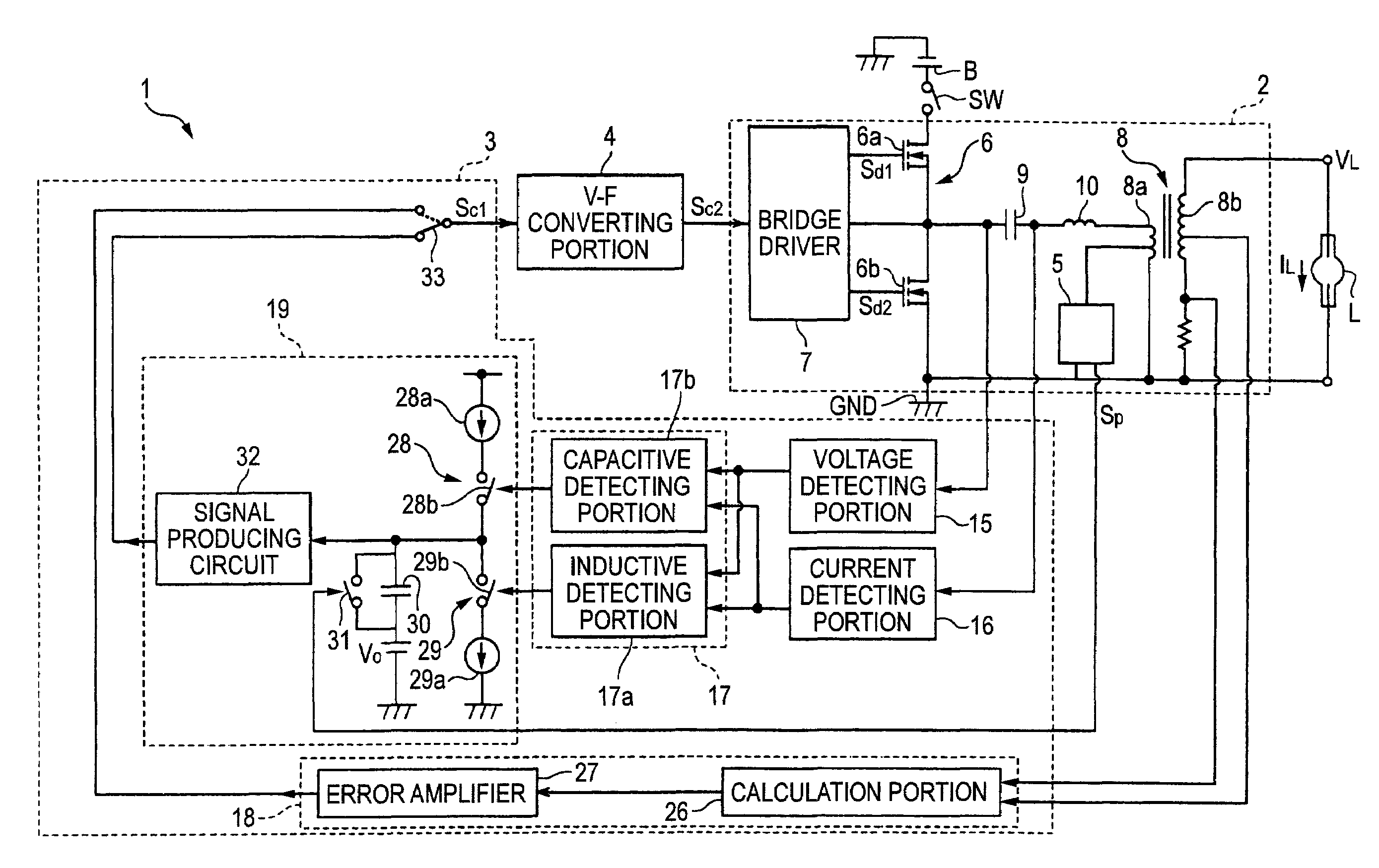
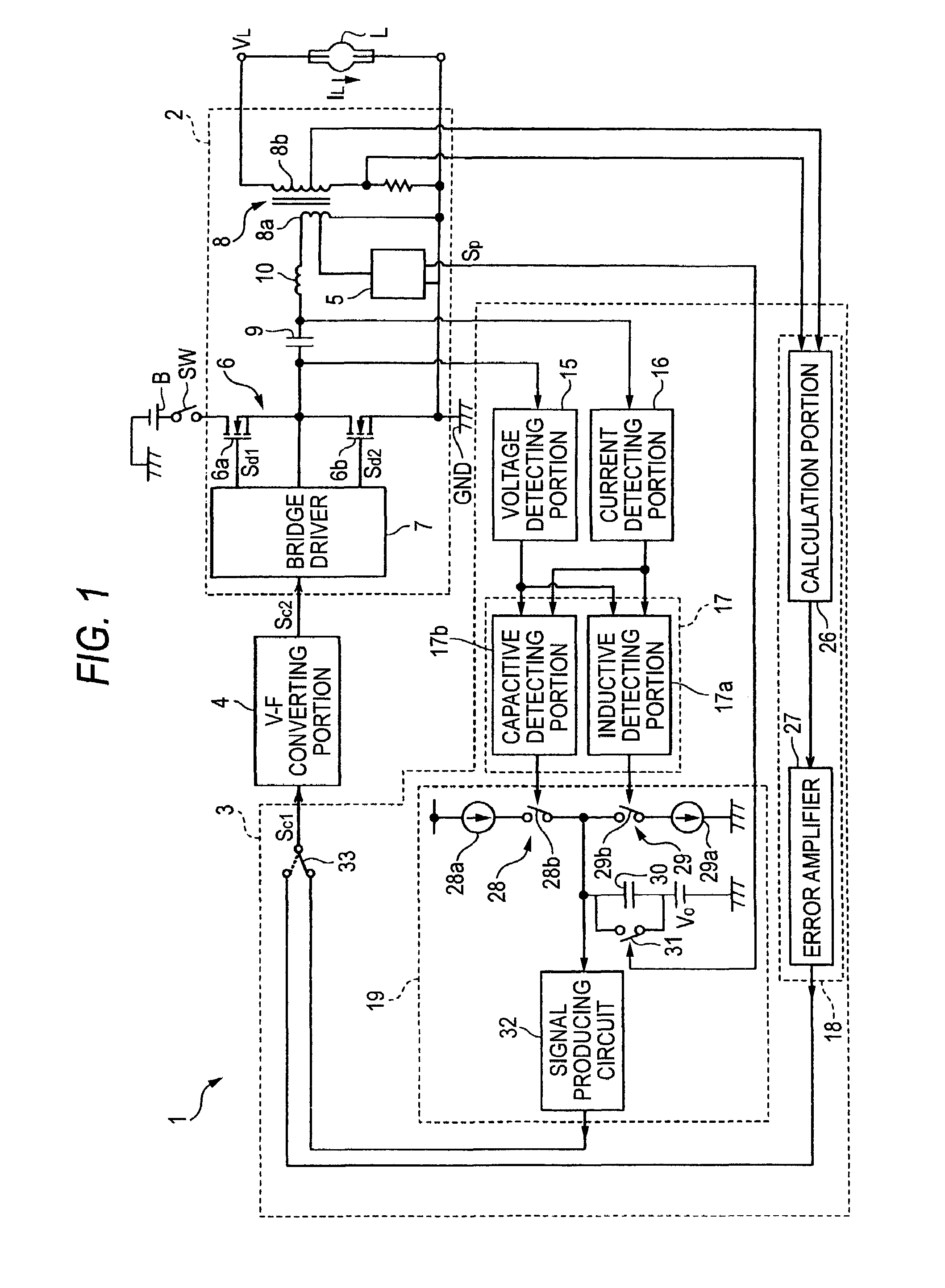
[0032]FIG. 1 is a block diagram showing a configuration of a discharge lamp lighting circuit according to an exemplary embodiment of the present invention. The discharge lamp lighting circuit 1 shown in FIG. 1 supplies an AC power for lighting a discharge lamp L, to the discharge lamp L, or converts a DC voltage from a DC power source B to an AC voltage, and supplies the AC voltage to the discharge lamp L. The discharge lamp lighting circuit 1 may, for example, be used in a lighting device for a vehicle, such as a head lamp. Moreover, the discharge lamp lighting circuit 1 may be used in a broad range of applications, basically wherever a head lamp i...


PUM


Abstract

A discharge lamp lighting circuit is provided. The discharge lamp lighting circuit includes a power supplying portion which comprises an inverter circuit comprising a switching element; a series resonant circuit comprising a capacitor, and at least one of an inductor and a transformer; and a driving circuit which drives said switching element, said power supplying portion converting DC power to AC power and supplying the AC power to a discharge lamp; and a controlling portion which produces a frequency control signal for controlling a frequency of a drive signal output from said driving circuit, the controlling portion including a phase difference detecting portion which detects a phase difference between an input voltage and an input current that are supplied from said inverter circuit to said series resonant circuit; and a control signal producing portion which produces the frequency control signal in accordance with the phase difference.

Description

[0001]This application claims priority from Japanese Patent Application No. 2006-346278, filed Dec. 22, 2006, in the Japanese Patent Office. The Japanese Patent Application No. 2006-346278 is herein incorporated by reference in its entirety.TECHNICAL FIELD[0002]Apparatuses consistent with the present invention relate to a discharge lamp lighting circuit.RELATED ART[0003]In order to light a discharge lamp such as a metal halide lamp used as a head lamp for a vehicle, a lighting circuit (i.e, a ballast) for stably supplying a power to the lamp is necessary. For example, Japanese Patent Unexamined Publication No. 2005-63821 shows a related art discharge lamp lighting circuit which includes a DC-AC converting circuit including a series resonant circuit. The DC-AC converting circuit supplies an AC power to a discharge lamp. The level of the supplied power is controlled by changing the driving frequency of the series resonant circuit.[0004]Related art discharge lamp lighting circuits also...

Claims


Application Information

Patent Timeline
Patent Type & Authority Patents(United States)
IPC IPC(8): G05F1/00
CPCH05B41/2925H05B41/2882
Inventor ICHIKAWA, TOMOYUKIMURAMATSU, TAKAO
Owner KOITO MFG CO LTD
Why Eureka
Try Eureka