Steam heat storage system

a technology of steam heat storage and steam, which is applied in the direction of steam generation using solar heat, steam generation using hot heat carriers, lighting and heating apparatus, etc., can solve the problems of reliability problems, increase the cost of solar plants, and loss of efficiency

Active Publication Date: 2017-06-20
COMMISSARIAT A LENERGIE ATOMIQUE ET AUX ENERGIES ALTERNATIVES
View PDF16 Cites 19 Cited by
  • Summary
  • Abstract
  • Description
  • Claims
  • Application Information

AI Technical Summary

Benefits of technology

[0020]Consequently, one purpose of the invention is to disclose a steam thermal storage system that is simpler than systems according to the state of the art, with improved dependability and better efficiency.
[0025]Association of a latent heat thermal storage reservoir and a liquid displacement reservoir has the advantage of providing instantaneous compensation for relatively long transients during the main cycle, i.e. the steam production cycle for example by the solar field, and particularly fast solar power transients caused by clouds passing in front of the sun. As soon as the steam quantity generated by a solar field reduces and is less than that required for optimum operation of the turbine, the required steam quantity is taken out of storage by the thermal storage system. With the invention, the presence of a large quantity of hot liquid in the liquid displacement reservoir is sufficient to maintain steam production over a relatively long time interval without a large variation of the operating pressure, while steam production in thermal storage systems in solar plants according to the state of the art over a relatively long period is only possible if it is accompanied by pressure reductions of the order of 10 to 20 bars.
[0026]In one very advantageous embodiment, the connection between the primary circuit or the high temperature module (when there is a high temperature module) and the latent heat thermal storage module is made through the top part of the liquid displacement reservoir at the steam blanket. This example embodiment has the advantage that it is simple to manufacture because the number of connections is reduced, and therefore the manufacturing cost is also reduced. At the same time, it enables a pressure equilibrium between the two reservoirs which will be an advantage later for more efficient compensation of pressure drops in the primary circuit.
[0035]The first transfer means may preferably include a distributor to inject or draw off liquid in or from the liquid displacement thermal storage module so as to reduce turbulence in the liquid volume.

Problems solved by technology

These exchangers cause losses of efficiency and also increase the cost of the solar plant.
However it has been found that this creates reliability problems and has a low efficiency.
Furthermore, thermal storage systems with direct steam generation according to the state of the art are more complex than oil storage systems.
This is why their estimated cost is higher than it is for oil units, for large plants.

Method used


Image

  • Steam heat storage system
  • Steam heat storage system
  • Steam heat storage system

Examples


Embodiment Construction

[0020]Consequently, one purpose of the invention is to disclose a steam thermal storage system that is simpler than systems according to the state of the art, with improved dependability and better efficiency.

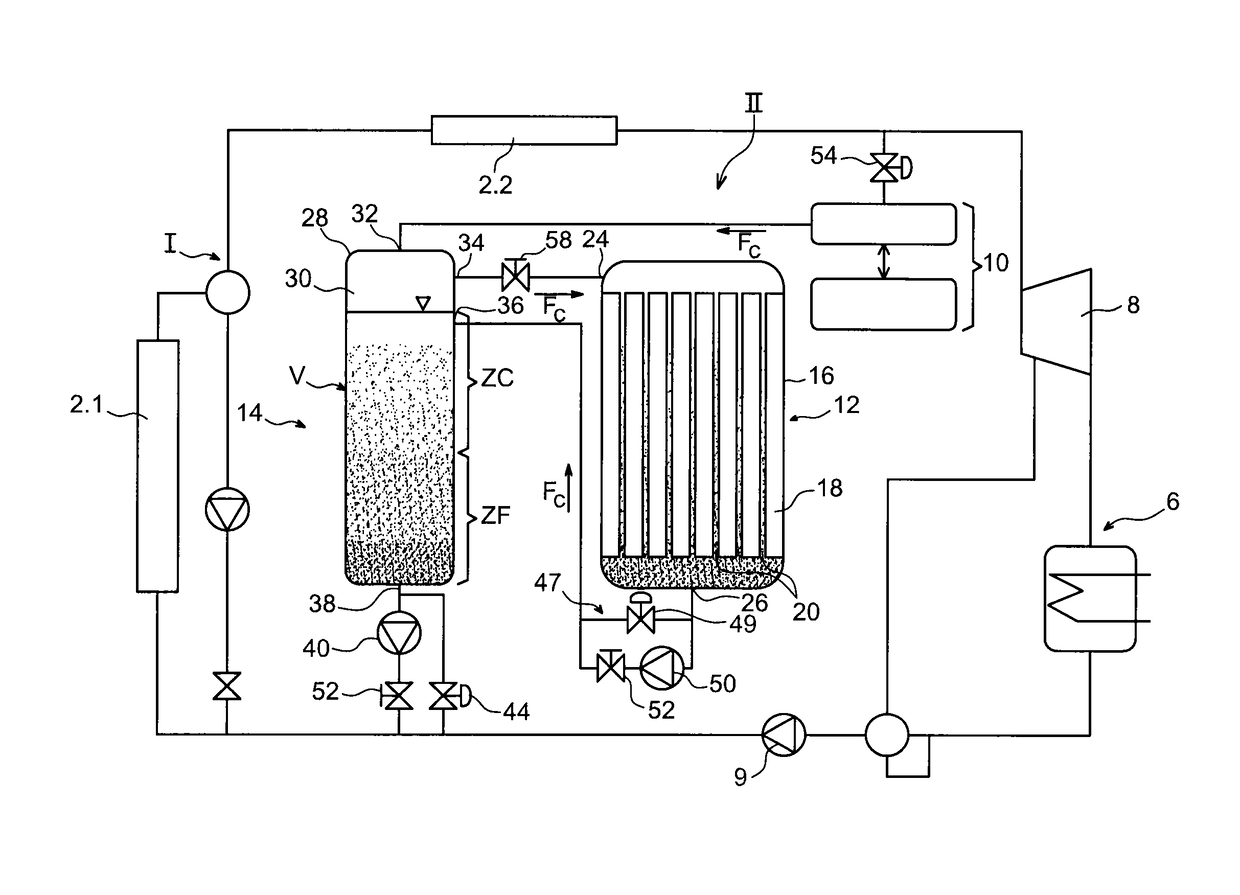
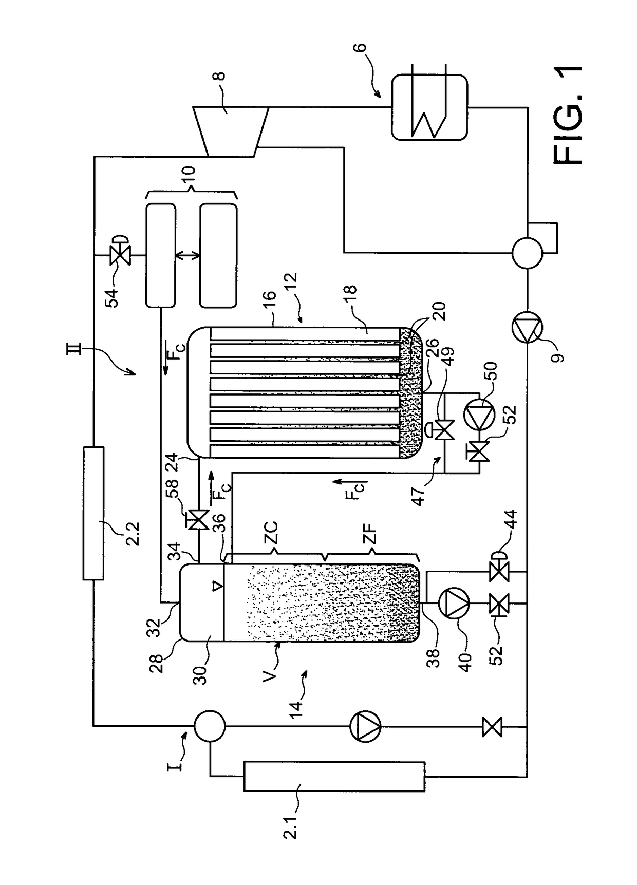
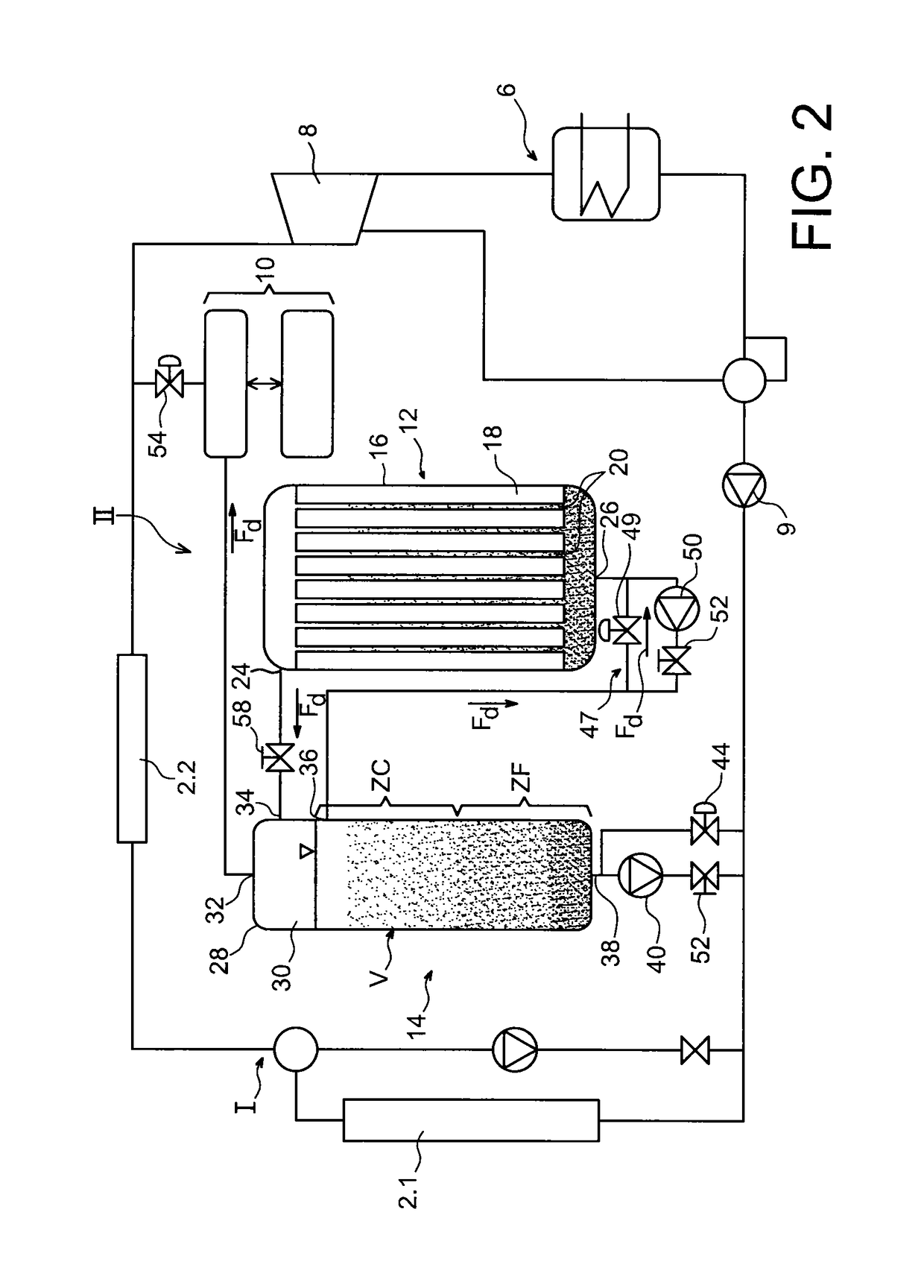
[0021]The purpose mentioned above is achieved by a steam thermal energy storage system comprising a first latent heat thermal energy storage reservoir and a second liquid displacement thermal energy storage reservoir, the liquid displacement thermal energy storage reservoir comprising a top zone full of steam and a bottom zone full of liquid, the first and the second reservoirs being connected such that steam entering the first reservoir after condensation during the charge phase, supplies the second reservoir with hot liquid in the bottom part full of liquid, and during the discharge phase, the lower part full of liquid from the second reservoir supplies the first reservoir with hot liquid, and such that the liquid and steam mix produced by the first reservoir passes through t...


PUM


Abstract

A solar plant including a solar field for production of steam, a turbine using steam, and an excess steam storage and draw off system. The system includes a latent heat thermal storage module and a liquid displacement thermal storage module including a liquid volume and a steam blanket. The modules are connected together so that the steam produced passes through the steam blanket before passing through the latent heat module, condensing, to be injected in the liquid volume, the lower part of the liquid volume being connected to the solar field and to an outlet of the turbine to let in or return cold liquid. The liquid volume acts as a liquid displacement reservoir.

Description

TECHNICAL FIELD AND PRIOR ART[0001]This invention relates to a steam thermal storage system and particularly to a direct solar steam generation plant comprising at least one such storage system.[0002]Focused solar thermal technology consists of using solar radiation to heat a fluid that acts directly or indirectly as a heat source in a thermodynamic cycle. Focusing makes it possible to reach more or less high temperatures and thus to benefit from more or less high thermodynamic conversion efficiencies.[0003]If the operation of focused thermodynamic solar plants is to be attractive for the generation of electrical power, it is essential to have high temperature thermal storage systems designed to store excess heat energy and to make it available for example when the intensity of the sunshine reduces.[0004]Consequently, it is required to manufacture thermal storage systems capable of:[0005]maintaining constant energy production during cloudy periods by minimising the number of turbine...

Claims


Application Information

Patent Timeline
Patent Type & Authority Patents(United States)
IPC IPC(8): F28D20/02F28D20/00F01K1/12F01K1/04F01K3/12F22B1/00F22B1/02F24J2/34F01K1/08F01K3/00F03G6/00F24S10/95
CPCF28D20/02F01K1/04F01K1/08F01K1/12F01K3/008F01K3/12F03G6/003F22B1/006F22B1/028F24J2/34F28D20/0039F28D20/021Y02E10/46F24S60/30F24S60/10Y02E60/14
Inventor OLCESE, MARCO
Owner COMMISSARIAT A LENERGIE ATOMIQUE ET AUX ENERGIES ALTERNATIVES
Why Eureka
Try Eureka