
Pulsed methods and systems for measuring the resistance of polarizing materials

a technology of polarizing materials and resistance, applied in the direction of resistance/reactance/impedence, instruments, measurement devices, etc., can solve the problems of residual polarization, inaccurate subsequent measurements, and relatively slow ac methods

Inactive Publication Date: 2009-07-21
ONSET COMP
View PDF4 Cites 45 Cited by
  • Summary
  • Abstract
  • Description
  • Claims
  • Application Information

AI Technical Summary

Benefits of technology

"The patent describes a system and method for measuring the resistance of a polarizing material. The system includes a voltage divider circuit and a processing unit. The processing unit drives the voltage divider circuit to measure the resistance of the polarizing material by applying a voltage across it and measuring the resulting voltage at a junction between the resistive element and the polarizing material. The data is then processed through an analog-to-digital converter and used to calculate the resistance of the polarizing material. The system can also be used to bleed off any residual polarization from the polarizing material after a measurement is completed. The technical effect of this patent is to provide a reliable and accurate method for measuring the resistance of polarizing materials, which can be useful in various applications such as optical devices and sensors."

Problems solved by technology

This polarization may be carried over to the subsequent measurements, making subsequent measurements inaccurate.
Using AC to measure the resistance of polarizing materials, however, requires electronics that are not commonly integrated into a microprocessor.
Furthermore, AC methods are relatively slow because both the positive and negative portions of the cycle are used.
However, when time between measurements is not sufficiently large, some residual polarization may remain.

Method used


Image

  • Pulsed methods and systems for measuring the resistance of polarizing materials
  • Pulsed methods and systems for measuring the resistance of polarizing materials

Examples


Embodiment Construction

[0012]Systems and methods for measuring the resistance of polarizing materials, such as for a relative humidity sensor, are disclosed. More specifically, systems and methods for measuring the resistance of polarizing materials using a voltage divider and pulsed excitation are disclosed.

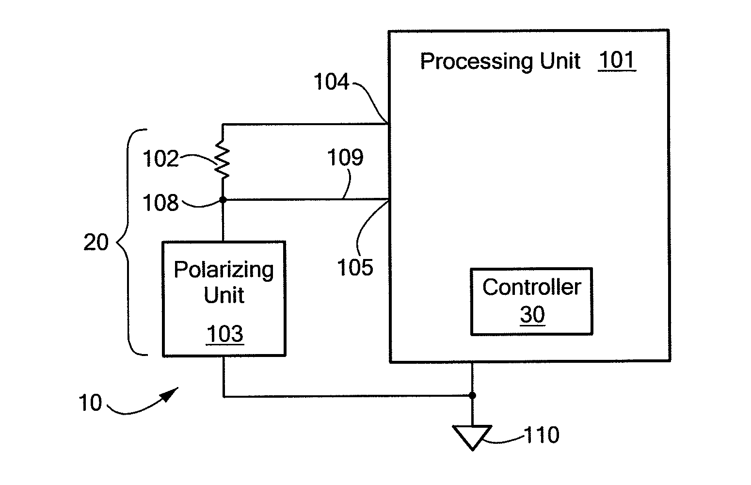
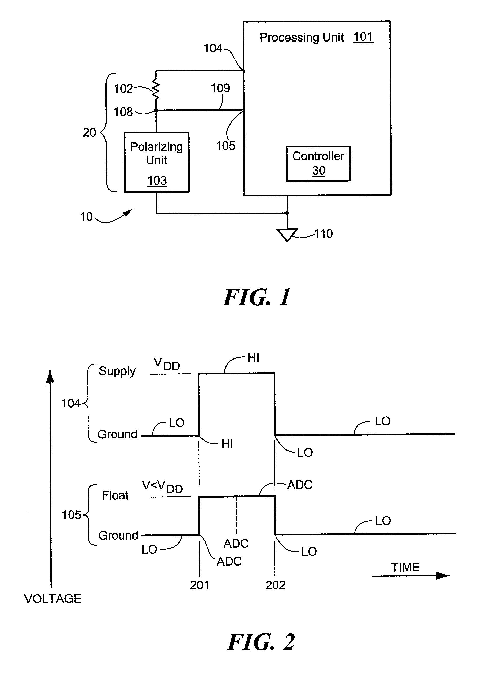
[0013]Referring to FIG. 1, a system 10 for measuring the resistance of a polarizing material is shown. The system 10 includes a voltage divider circuit 20 and a processing unit 101.

[0014]The processing unit 101, such as a microprocessor, includes a voltage (power) source, a central processing unit (CPU), random access memory (RAM), read-only memory (ROM), and a controller 30. Voltage sources, CPUs, ROM, RAM, and controllers 30 for a processing unit 101, especially for a microprocessor, are all well-known in the art and will not be described in detail. The operation of the controller 30 and its interaction with the other elements of the system 10 will be described in greater detail below.

[0015]The volt...


PUM


Abstract

A system and method for measuring resistance of a polarizing material are disclosed. The system includes a voltage divider circuit having a first resistive element of known resistance and the polarizing material of unknown resistance and a processing unit. The processing unit is electrically-coupled to the voltage divider circuit and adapted to apply a voltage across the voltage divider circuit. A first input / output (I / O) pin is electrically-coupled between the processing unit and the first resistive element. A second pin is electrically-coupled between the processing unit and a junction between the polarizing material and the first resistive element. A controller is adapted to cause the second pin to short the polarizing material after a measurement is completed, to bleed off any residual polarization from the capacitive element of the polarizing material.

Description

CROSS REFERENCE TO RELATED APPLICATIONS[0001]Priority to U.S. provisional patent application 60 / 763,505 entitled “Improved Pulsed Method for Measuring the Resistance of Polarizing Materials” filed Jan. 31, 2006 is claimed.STATEMENT REGARDING FEDERALLY SPONSORED RESEARCH OR DEVELOPMENT[0002]Not ApplicableBACKGROUND OF THE INVENTION[0003]Polarizing materials, such as those used for measuring relative humidity, can be thought of as a resistive element and a capacitive element operatively-coupled in series. Determining the resistance of the polarizing material requires applying a voltage, which will partially add charge to a capacitive element. This polarization may be carried over to the subsequent measurements, making subsequent measurements inaccurate.[0004]Conventional methods of measuring the resistance of polarizing materials have used alternating current (AC). With an AC methodology, polarization built up in the capacitive element during the positive portion of the cycle is undon...

Claims


Application Information

Patent Timeline
Patent Type & Authority Patents(United States)
IPC IPC(8): G01R27/08
CPCG01R27/02
Inventor HOCKER, LON
Owner ONSET COMP
Learn More