

Loop back plug and method
a technology of loop back plugs and back plugs, applied in the direction of optical apparatus testing, instruments, photomechanical equipment, etc., can solve the problems of increasing network reliability, reducing network complexity and cost, and time-consuming manual splicing
- Summary
- Abstract
- Description
- Claims
- Application Information
AI Technical Summary
Benefits of technology
Problems solved by technology
Method used
Image

Examples
Embodiment Construction
[0026]The following detailed description of implementations consistent with the principles of the invention refers to the accompanying drawings. The same reference numbers in different drawings may identify the same or similar elements. Also, the following detailed description does not limit the invention. Instead, the scope of the invention is defined by the appended claims and their equivalents.
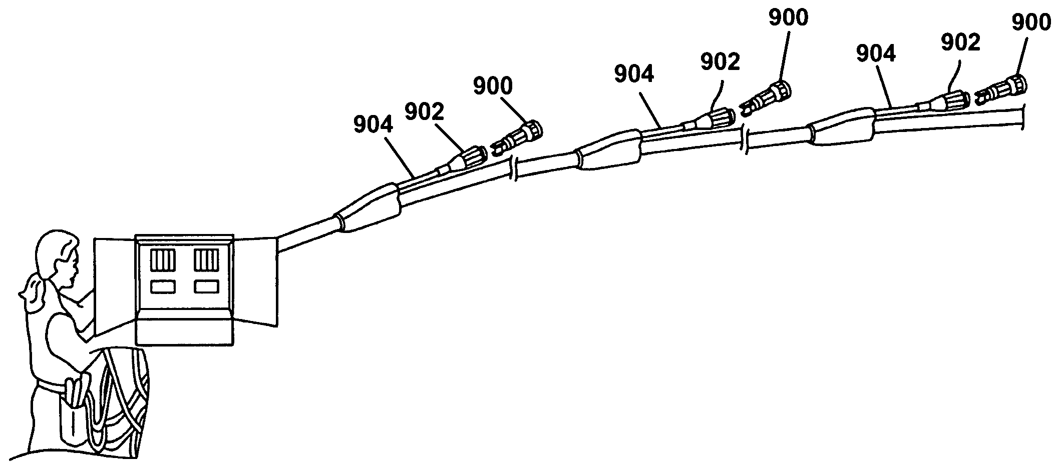
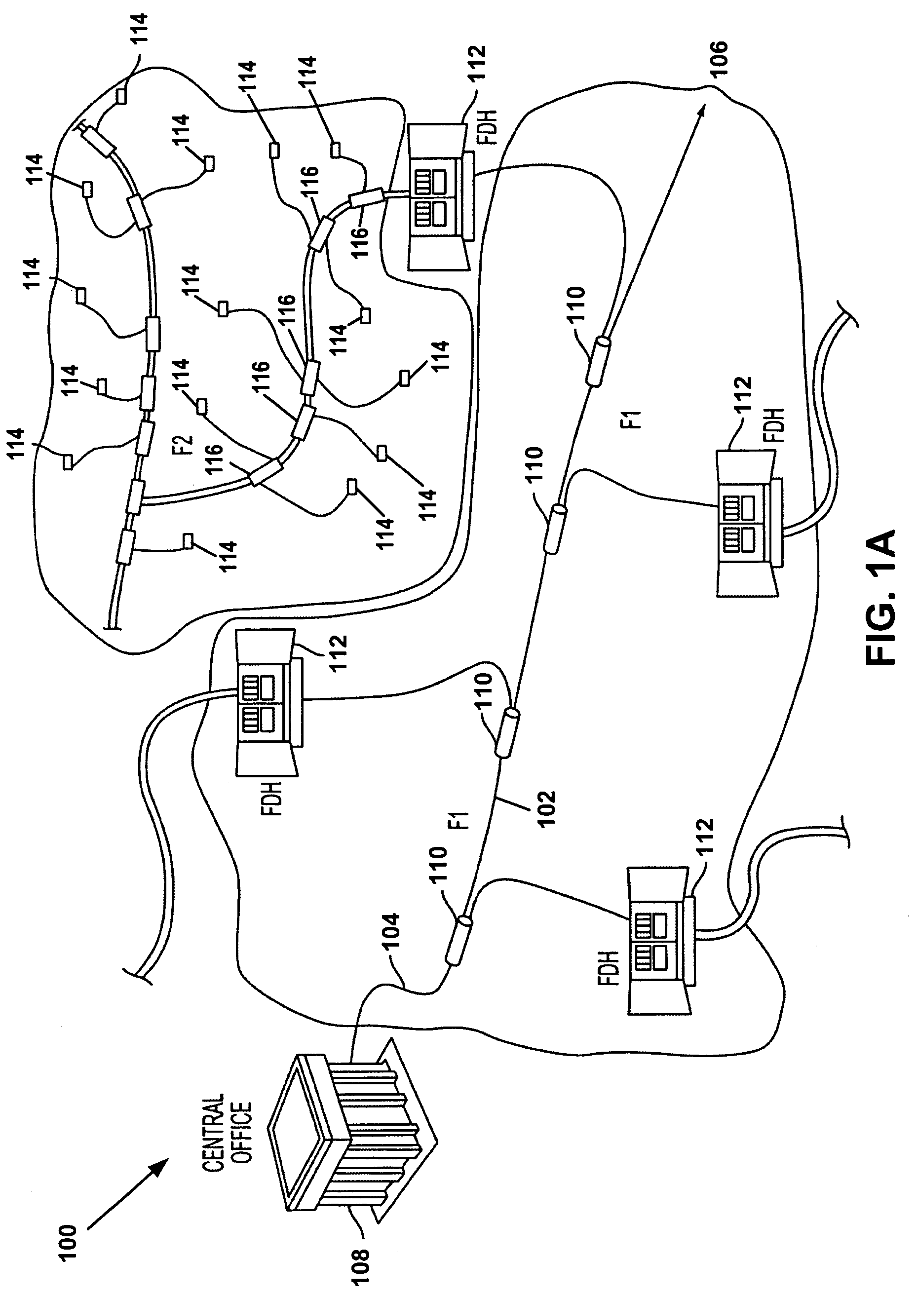
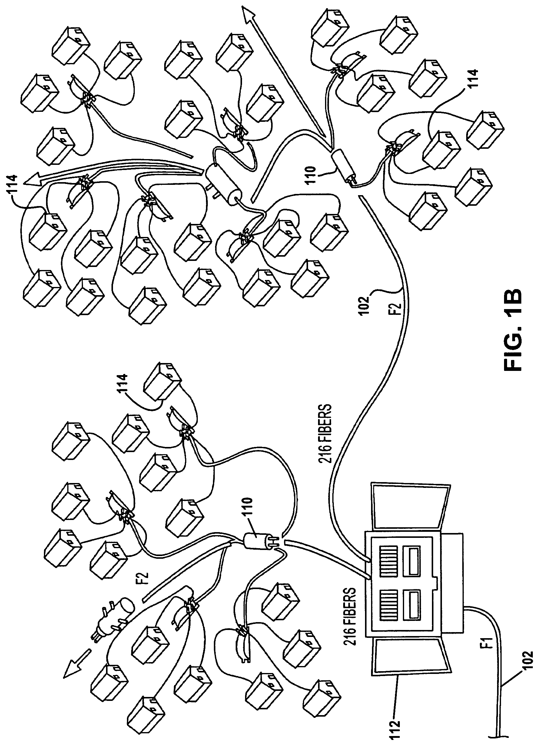
[0027]FIGS. 1A-C illustrate exemplary networks 100 that may use factory integrated terminations consistent with the principles of the invention. A fiber distribution cable 102 may include a proximal end 104 and a distal end 106. The proximal end 104 may be associated with a central office 108 and may act as the beginning of the distribution cable 102. The distal end 106 may be located some distance away from the proximal end 104 and may act as the end of the distribution cable 102. One or more splices 110 may be located between the proximal end 104 and distal end 106 of the distribution cab...
PUM
 Abstract
Description
Claims
Application Information