Jib boom

a boom and boom technology, applied in the field of jib boom, can solve the problem of not being able to facilitate the tensioning of the sail leech

Inactive Publication Date: 2009-07-28
HOYT JOHN GARRISON
View PDF12 Cites 2 Cited by
  • Summary
  • Abstract
  • Description
  • Claims
  • Application Information

AI Technical Summary

Benefits of technology

[0005]In this regard, the present invention preserves the advantages of prior art spinnaker poles and combines such a spinnaker pole with a jib boom. The present invention therefore provides new advantages of a self tacking, self vanging jib boom that off wind also works as a spinnaker pole to extend and control the luff of an asymmetrical spinnaker. Further, the present invention overcomes not only many disadvantages of such currently available and unwieldy spinnaker poles but also offers the same self vanging and ease of trimming a jib.
[0009]It is a further object of the present invention to simplify the hoisting and jibing of a spinnaker.
[0010]It is a further object of the present invention to locate the tack of a jib at the forward end of the jib boom beyond the rotational shaft to project the luff to windward when off the wind and reduce weather helm.

Problems solved by technology

The difficulty was that while such a jib boom served to assist in projecting maximum sail area, they did not facilitate tensioning of the leech of the sail.
This arrangement also has difficulties in that many sailboats are rigged to carry spinnakers that are useful off the wind and particularly downwind.

Method used


Image

  • Jib boom
  • Jib boom
  • Jib boom

Examples


Embodiment Construction

[0021]The novel features which are characteristic of the present invention are set forth in the appended claims. However, the invention's preferred embodiments, togetherwith further objects and attendant advantages, will be best understood by reference to the following detailed description taken in connection with the accompanying drawings.

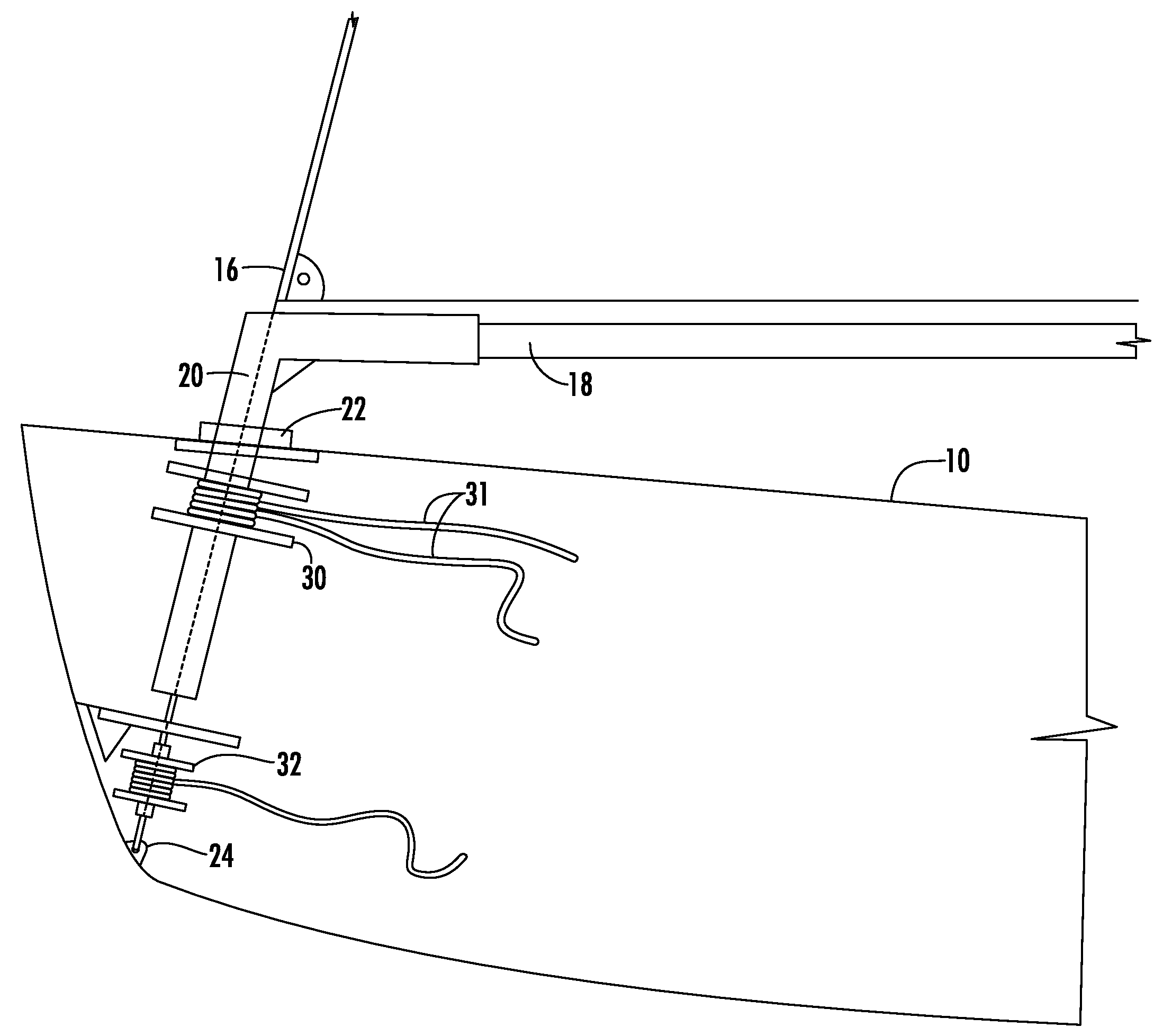
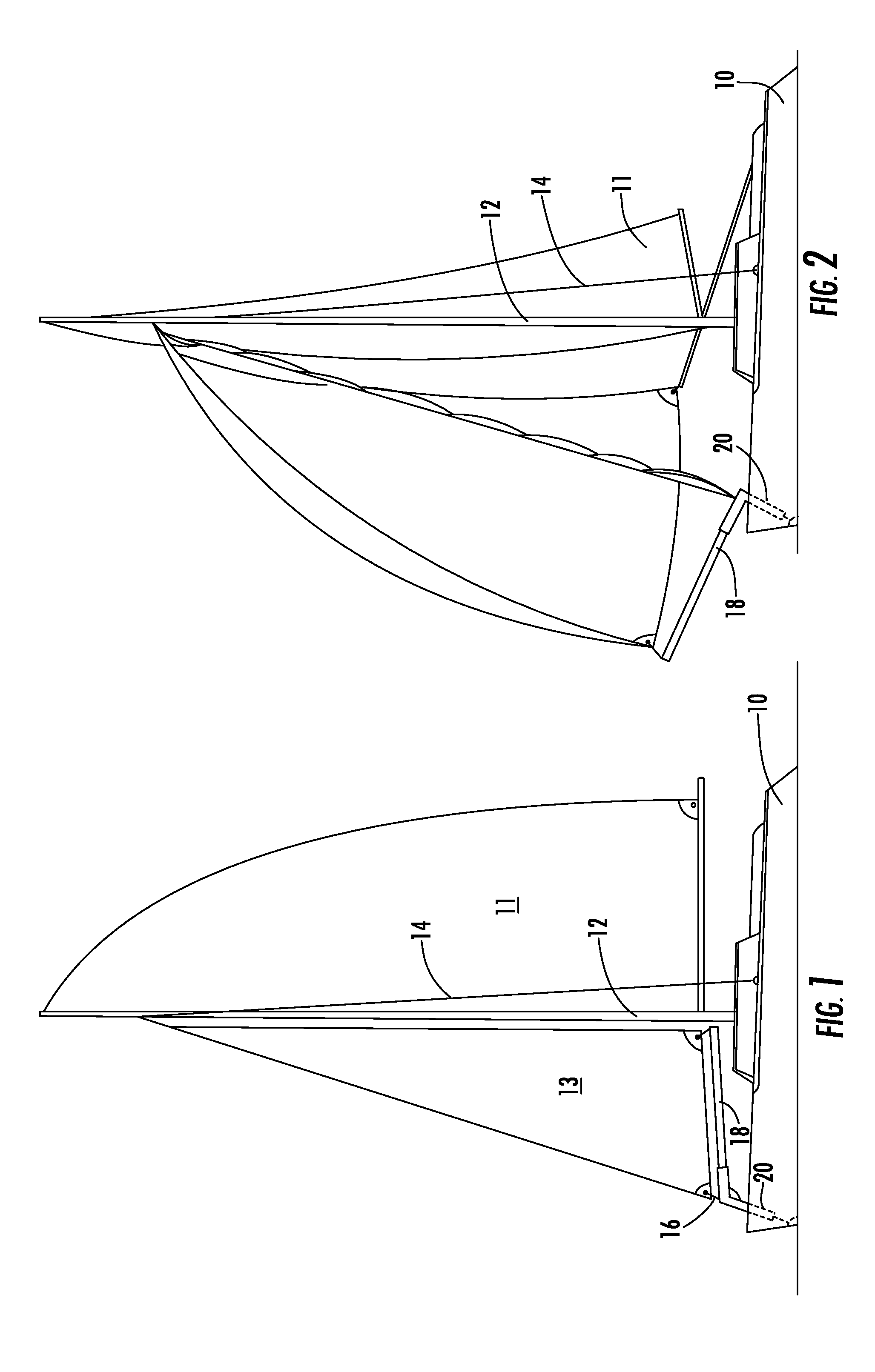
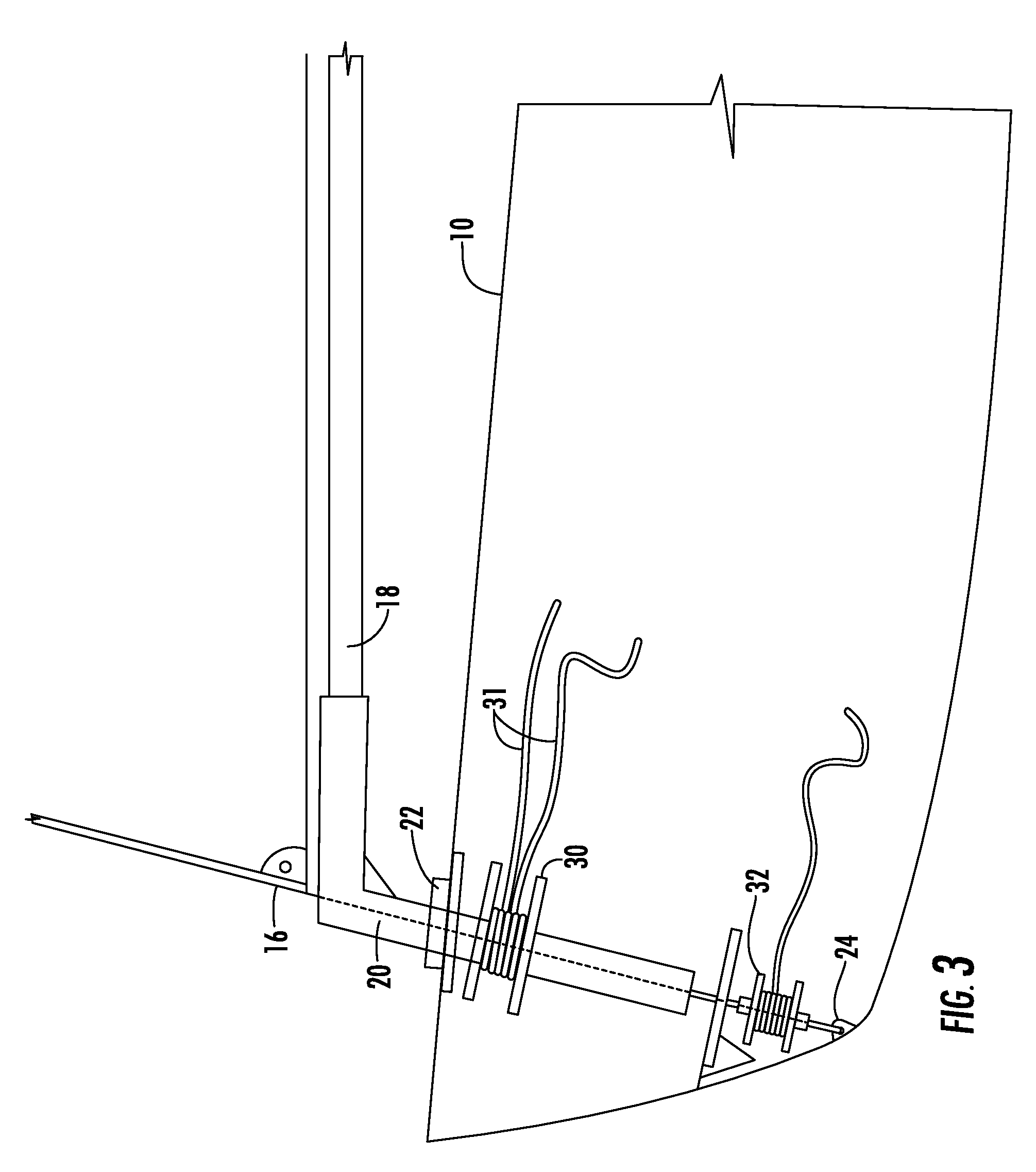
[0022]The drawings show port side views of the sailboat 10 with a mainsail 11 and a jib sail 13. A mast 12 is provided with the usual shrouds 14 and a jib stay 16. The jib boom 18 has a stub shaft 20 that is received in bearing means 22. The jib stay 16 passes through the center of the jib boom stub shaft and is fastened to the mast and to the hull of the boat as at 24. With this configuration this places the center of rotation at the luff 15 of the jib, which insures constant control of leech tension on all points of sail.

[0023]Since the jib boom rotationally embraces the forestay 16 this allows a spinnaker boom to be carried by the jib boom. Ref...


PUM


Abstract

A sailboat having a free standing jib boom mounted on a stub shaft, which rotates about an axis coextensive with the jib stay. The boom may extend not only aft of the stub shaft but also forward allowing unique rig configurations.

Description

CROSS-REFERENCE TO RELATED APPLICATIONS[0001]This application is related to and claims priority from earlier filed U.S. Provisional Patent Application No. 60 / 889,751, filed Feb. 14, 2007.BACKGROUND OF THE INVENTION[0002]The present relates generally to a jib boom for use on sailing vessels. In the past, conventional jib booms are generally affixed to a pedestal at the bow of the boat by a universal joint. The difficulty was that while such a jib boom served to assist in projecting maximum sail area, they did not facilitate tensioning of the leech of the sail. To overcome this problem, U.S. Pat. No. 5,463,969 discloses a jib boom that yields constant leech tension and it results in essentially a self-tacking vanged jib where the clew is held down. This arrangement also has difficulties in that many sailboats are rigged to carry spinnakers that are useful off the wind and particularly downwind. These are essentially triangular sails and have been generally known as symmetrical spinnak...

Claims


Application Information

Patent Timeline
Patent Type & Authority Patents(United States)
IPC IPC(8): B63H9/10
CPCB63H9/1071
Inventor HOYT, JOHN GARRISON
Owner HOYT JOHN GARRISON
Why Eureka
Try Eureka