Control of animal containment system transmitter settings with minimal switches

a technology for controlling the setting of the transmitter and the containment system, which is applied in the field of animal containment system transmitters, can solve the problems of increasing the number of switches, increasing the cost and aesthetics of the enclosure, and needing to be a difference in the correction signal emitted by the outdoor loop, so as to achieve the effect of increasing the number of features and functions, low component cost and high reliability

Active Publication Date: 2009-07-28
RADIO SYST CORP
View PDF12 Cites 22 Cited by
  • Summary
  • Abstract
  • Description
  • Claims
  • Application Information

AI Technical Summary

Benefits of technology

[0013]An advantage of the present invention is that it can accommodate an increasing number of features and functions of the animal training system without increasing the number of switches.
[0014]Another advantage of the present invention is that it can accommodate an increasing number of features and functions of the animal training system without changing the basic design of the transmitter.
[0015]Yet another advantage of the present invention is that it can accommodate an increasing number of features and functions of the animal training system without changing the transmitter circuit board.
[0016]Yet another advantage of the present invention is that it provides a higher reliability.
[0017]Yet another advantage of the present invention is that it provides a relatively low component cost.
[0018]Yet another advantage of the present invention is a more aesthetically attractive appearance.

Problems solved by technology

Also, a containment loop can be installed indoor, and there may need to be a difference in the correction signal emitted by the outdoor loop versus the indoor loop, as there may be more serious consequences to the animal for leaving the outdoor containment area, or vice versa.
Firstly, as the number of features and functions grow, the number of switches also has to grow, which can be costly and aesthetically unattractive.
Another problem is that there may not be enough room within the transmitter or on the transmitter circuit board for a switch for each functional category, particularly as the number of system features and functions grow.
Further, as the number of components increases, i.e., the number of switches increases, the reliability of the system tends to decrease.
Yet further, adding a switch for each additional feature and / or function requires design changes to the transmitter, which are costly and time consuming.

Method used


Image

  • Control of animal containment system transmitter settings with minimal switches
  • Control of animal containment system transmitter settings with minimal switches
  • Control of animal containment system transmitter settings with minimal switches

Examples


Embodiment Construction

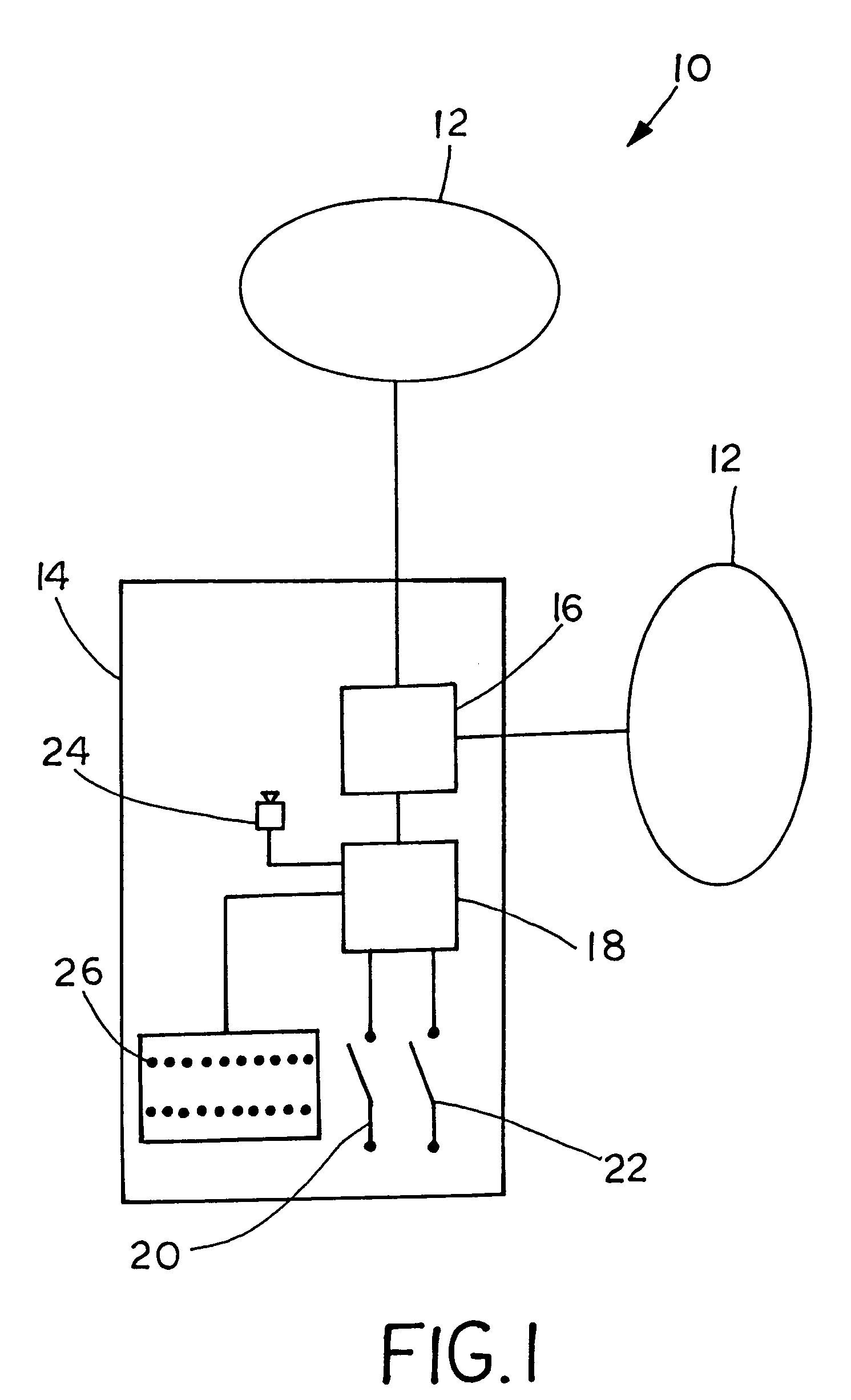
[0030]Referring now to the drawings, and more particularly to FIG. 1, there is shown an animal training system 10, which generally includes at least one antenna 12, and a transmitter 14 connected to antennas 12. Transmitter 14 includes a modulator 16 for energizing antenna 12, a controller 18 connected to modulator 16, a first switch 20 connected to controller 18, which can be a momentary pushbutton for example, and a second switch 22 connected to controller 18 which also can be a momentary pushbutton, for example. An enunciator 24, such as piezo-electric device, can be connected to controller 18 to provide a chirp for feedback to a user whenever one of switches 20, 22 are pressed. Indicator lights 26 can provide visual feedback for a user when using switches 20, 22 to select settings for transmitter 14. The common terminal of switches 20, 22 can be connected to a ground or voltage source, for example.

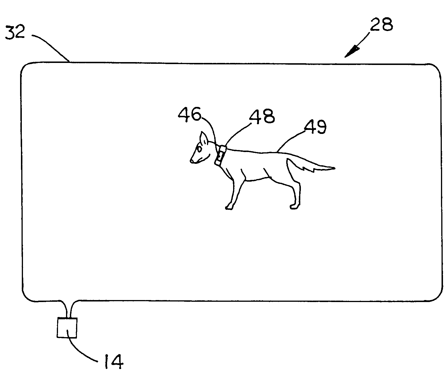
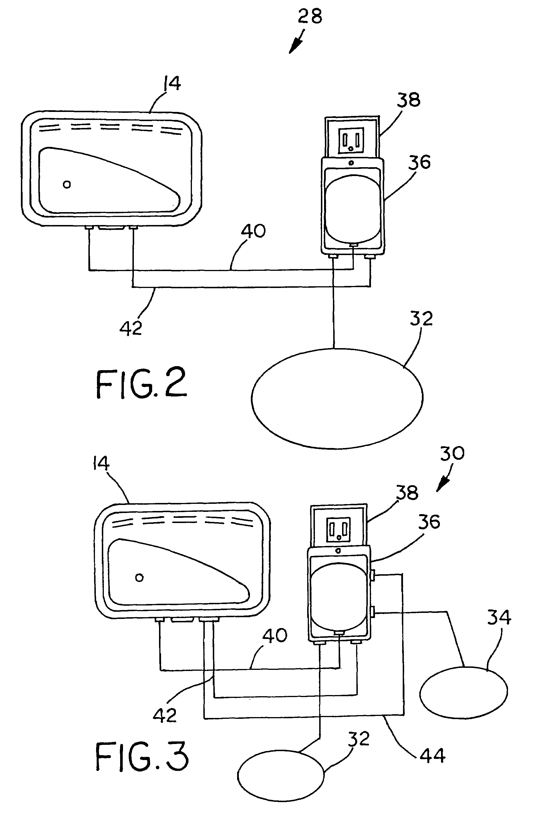
[0031]FIGS. 2 and 3 illustrate embodiments of installations of animal training sys...


PUM


Abstract

A transmitter for an animal training system, which includes a modulator for energizing at least one antenna, and a controller connected to the modulator. A first switch is connected to the controller, and the first switch is for entering a setup mode and for selecting at least one of a plurality of setting configurations. A second switch is also connected to the controller, and the second switch is for modifying a value of a respective setting configuration.

Description

BACKGROUND OF THE INVENTION[0001]1. Field of the Invention[0002]The present invention relates to animal training systems, and, more particularly, to transmitters for animal containment systems.[0003]2. Description of the Related Art[0004]Animal training systems are known for containing a pet dog, or other animals, within a defined region without the need for a physical barrier such as a fence. An example of such a system includes a wire loop buried around the perimeter of an area, which has the two wire ends energized by a transmitter power source. The animal has a collar with a receiver which senses the signal radiated by the wire loop and provides a correction signal to the animal when the animal is within a predetermined relatively short range of the wire loop. The correction signal can be a tone, a vibration, and / or an electrical stimulation, for example. The animal learns to avoid the correction signal by staying within a perimeter defined by the wire loop signal, and the need ...

Claims


Application Information

Patent Timeline
Patent Type & Authority Patents(United States)
IPC IPC(8): A01K15/04
CPCA01K15/023A01K15/021
Inventor MOORE, WILLIAM P.
Owner RADIO SYST CORP
Why Eureka
Try Eureka