Electrically operated vehicle drive controller and electrically operated vehicle drive control method

a technology of electric drive controller and electric drive motor, which is applied in the direction of vehicle position/course/altitude control, process and machine control, instruments, etc., can solve the problems of increased vibration, delay caused by calculation of angular acceleration, and inability to restrain vibration, so as to reduce the generation of vibration in the vehicle drive unit

Active Publication Date: 2009-07-28
AISIN AW CO LTD
View PDF16 Cites 17 Cited by
  • Summary
  • Abstract
  • Description
  • Claims
  • Application Information

AI Technical Summary

Benefits of technology

[0009]An object of the invention is to solve the problems of the conventional electrically operated vehicle drive controller, and provide an electrically operated vehicle drive controller and an electrically operated vehicle drive control method able to reliably compensate for the excessive and deficient amounts of the output torque with respect to the vehicle request torque by driving the drive motor, and restrain the generation of the vibration in the vehicle drive unit.
[0025]In this case, when the drive motor target torque is generated on the basis of the inertia correction torque and the drive motor is driven and vibration is generated in the electrically operated vehicle, the damping torque is generated and the output torque is corrected. Accordingly, it is possible to reliably compensate for the excessive and deficient amounts of the output torque with respect to the vehicle request torque, and restrain the generation of vibration in a vehicle drive unit.

Problems solved by technology

However, when the filter is used in calculating the angular acceleration, the disturbance component of the noise shape can be removed, but delay is caused in the calculation of the angular acceleration and vibration can not be restrained.
Further, there is a case in which the vibration is increased.

Method used


Image

  • Electrically operated vehicle drive controller and electrically operated vehicle drive control method
  • Electrically operated vehicle drive controller and electrically operated vehicle drive control method
  • Electrically operated vehicle drive controller and electrically operated vehicle drive control method

Examples


first embodiment

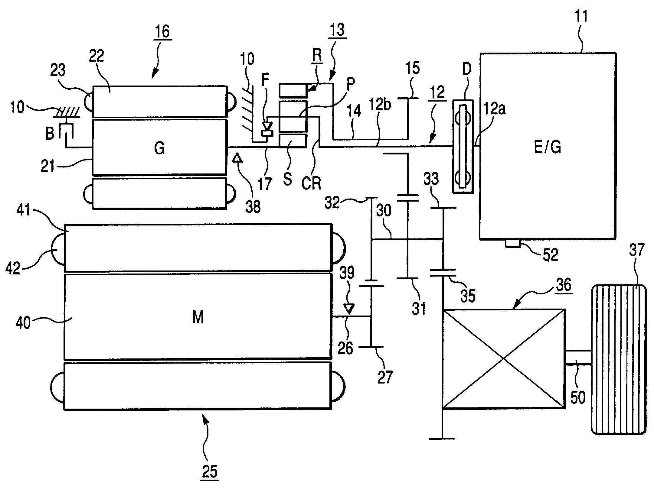
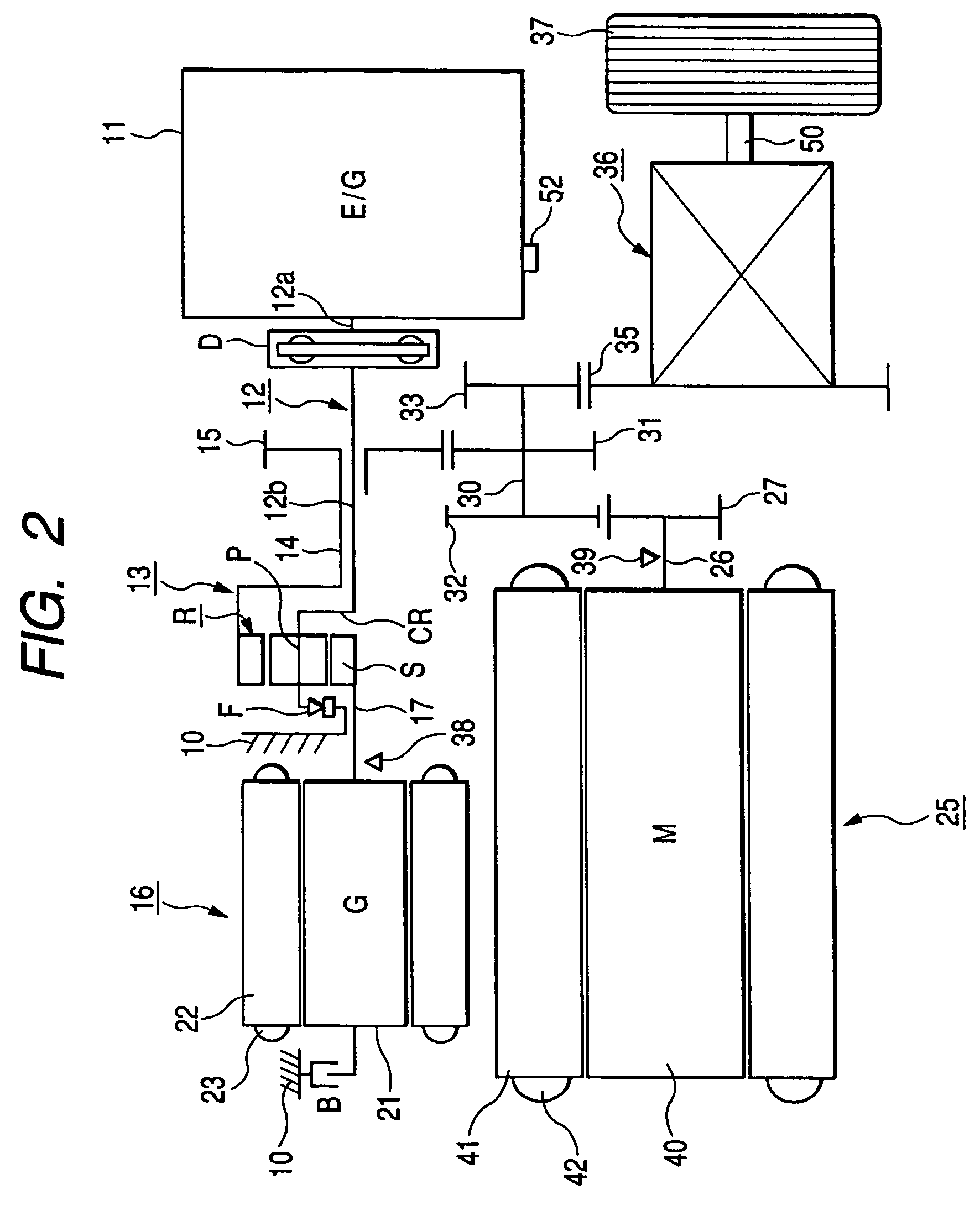
[0044]FIG. 2 is a conceptual view of the hybrid vehicle of the invention.

[0045]In this figure, reference numerals 11 and 12 respectively designate an engine (E / G) (as a driving source) arranged on a first axis and an output shaft, arranged on the first axis, which outputs rotation generated by driving the engine 11. Reference numeral 13 designates a planetary gear unit (as a differential rotating device), arranged on the first axis, which changes speeds with respect to the rotation inputted through the output shaft 12. Reference numeral 14 designates an output shaft arranged on the first axis, and the rotation after the speed change in the planetary gear unit 13 is outputted to the output shaft 14. Reference numeral 15 designates a first counter drive gear (as an output gear) fixed to the output shaft 14. Reference numeral 16 designates an electric generator (G) (as a driving source) and a first electrically operated machine, arranged on the first axis, which connects to the planeta...

second embodiment

[0157]the invention will next be explained.

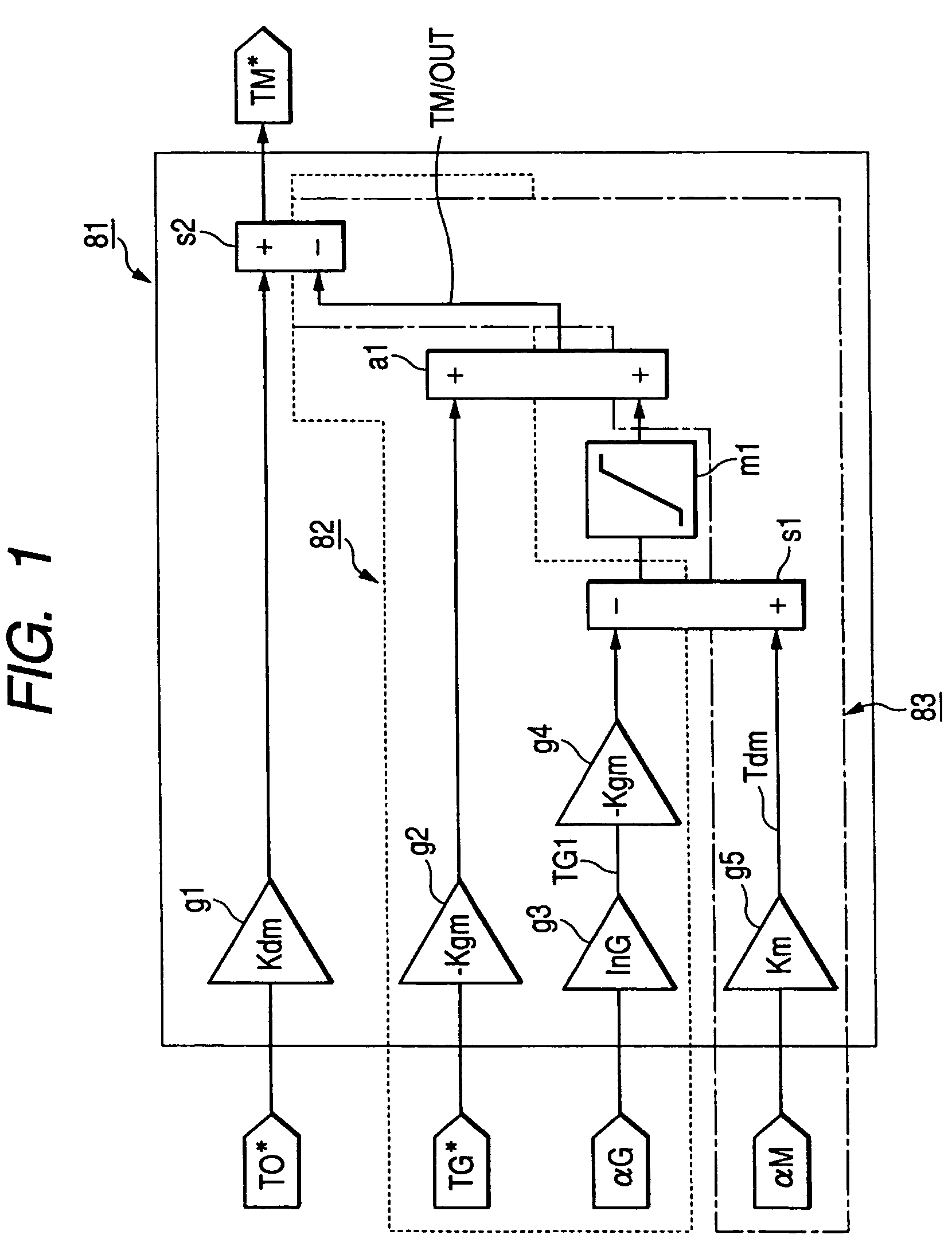
[0158]FIG. 16 is a view showing a drive motor target torque calculation processing section of the second embodiment of the Invention.

[0159]In this figure, reference numeral 81 designates a drive motor target torque calculating section as a drive motor target torque calculation processing means. Reference numerals g11 to g14 designate multipliers, and reference numerals s11 and s12 designate subtracters. Reference numerals m11 and a11 respectively designate a limiter and an adder. Reference numeral 82 designates an inertia correction processing section as an inertia correction processing means. This inertia correction processing section 82 has multipliers g12 and g14, the subtracters s1 and s12 and the adder a11. Reference numeral 83 designates a damping torque correction processing section as a damping torque correction processing means. This damping torque correction processing section 83 has the multiplier g13, the subtracter s12, and the...


PUM


Abstract

An electrically operated vehicle drive controller has an electric generator target torque calculation processing means for calculating electric generator target torque TG*; an inertia correction torque calculation processing means for calculating inertia correction torque on the basis of inertia torque TGI of an electric generator; a drive motor target torque generation processing means for generating drive motor target torque on the basis of the calculated inertia correction torque; and a damping torque correction processing means for correcting output torque on the basis of an output torque changing index which expresses a change of output torque due to the inertia correction torque.

Description

[0001]This application claims priority to Japanese Patent Application JP 2004-181758, filed in the Japanese Patent Office on Jun. 18, 2004, the disclosure of which is incorporated herein by reference.BACKGROUND OF THE INVENTION[0002]1. Field of the Invention[0003]The present invention relates to an electrically operated vehicle drive controller and an electrically operated vehicle drive control method.[0004]2. Background Art[0005]A planetary gear unit having a sun gear, a ring gear and a carrier is conventionally arranged in a vehicle drive unit mounted to a hybrid vehicle as an electrically operated vehicle and transmitting one portion of engine torque (as torque of an engine) to an electric generator (electric generator motor) and transmitting the remaining engine torque to a drive wheel. The sun gear and the electric generator are connected to each other. The ring gear, a drive motor and the drive wheel are connected to each other. The carrier and the engine are connected to each...

Claims


Application Information

Patent Timeline
Patent Type & Authority Patents(United States)
IPC IPC(8): B60K1/02B60K1/00B60K6/445B60L50/16B60L15/20B60W10/06B60W10/08B60W20/00
CPCB60K6/445B60W10/06B60W10/08B60W30/20Y02T10/6239Y02T10/6286Y02T10/7258B60W20/00Y02T10/62Y02T10/72B60W20/10
Inventor HISADA, HIDEKIHARA, TAKESHINOMURA, MASAKI
Owner AISIN AW CO LTD
Why Eureka
Try Eureka