Ink transfer device for a printing press

a printing press and transfer device technology, applied in printing, office printing, printing blankets, etc., can solve the problems of cylinder oscillation, high mechanical effort of the transfer device based on rubber sleeves, and relatively high cost, so as to minimize the risk of cylinder oscillation, minimize the gap between non-ink-carrying parts, and high print quality

Inactive Publication Date: 2009-08-04
MANROLANAD AG
View PDF11 Cites 0 Cited by
  • Summary
  • Abstract
  • Description
  • Claims
  • Application Information

AI Technical Summary

Benefits of technology

[0010]In the spirit of the present invention, an ink transfer device based on rubber blankets is proposed with which non-ink-carrying gaps can be minimized. This makes it possible, even in the case of ink transfer devices which are based on rubber blankets, to minimize the risk of cylinder oscillations and in this way to provide high print qualities. With the ink transfer device according to the invention, non-ink-carrying gaps between the leading end and the trailing end of the rubber blanket can be realized which have a width in the circumferential direction between 0 mm and 1.0 mm. This makes it possible to combine the advantages of ink transfer devices based on rubber sleeves, specifically the minimal tendency to oscillations of the same, with the advantages of ink transfer devices based on rubber blankets, specifically the cost-effective implementation of the same.

Problems solved by technology

Ink transfer devices based on rubber sleeves require a great deal of mechanical effort, however, and are therefore relatively expensive.
During the clamping, non-ink-transferring gaps or channels are formed in between what is known as a leading end and what is known as a trailing end of the rubber blanket, and have a detrimental influence on the rolling behavior of printing cylinders and thus, in particular in the case of relatively slim cylinders and in the case of relatively high rotational speeds of the same, can cause cylinder oscillations.
Ink transfer devices based on rubber blankets are certainly less expensive but the print quality that can be realized is restricted with regard to oscillation stripes as compared with ink transfer devices based on rubber sleeves.

Method used


Image

  • Ink transfer device for a printing press
  • Ink transfer device for a printing press
  • Ink transfer device for a printing press

Examples


Embodiment Construction

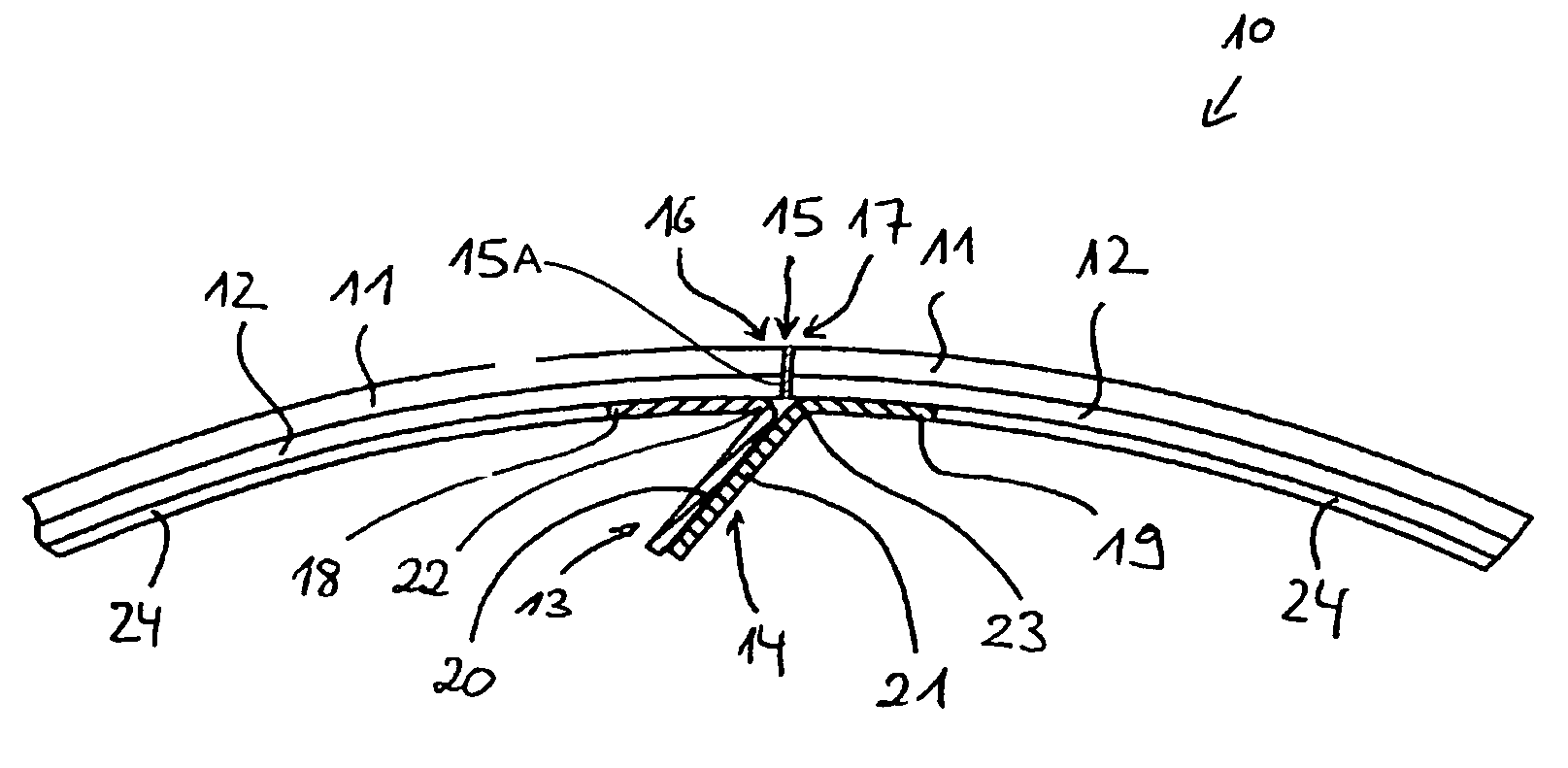
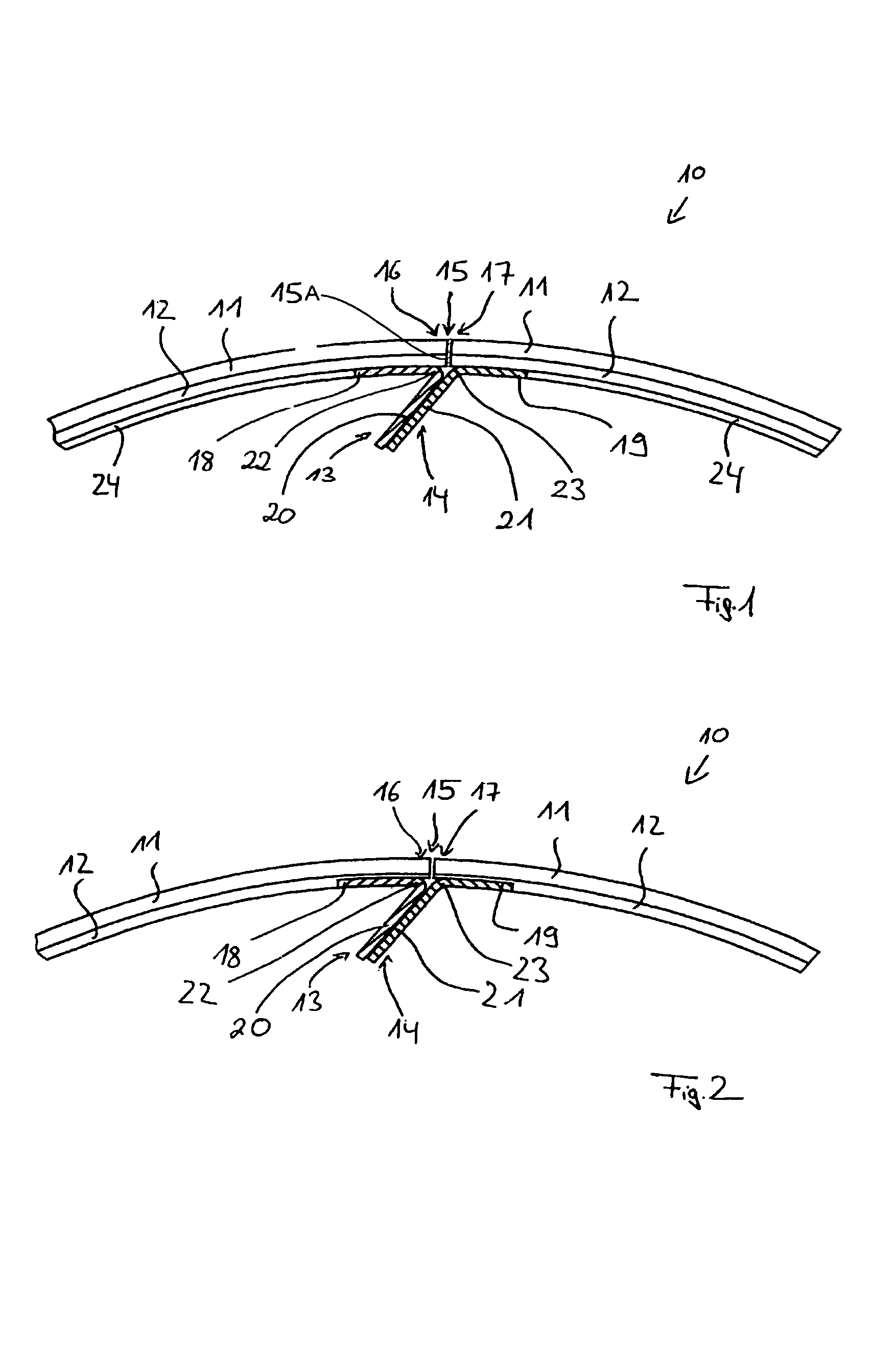
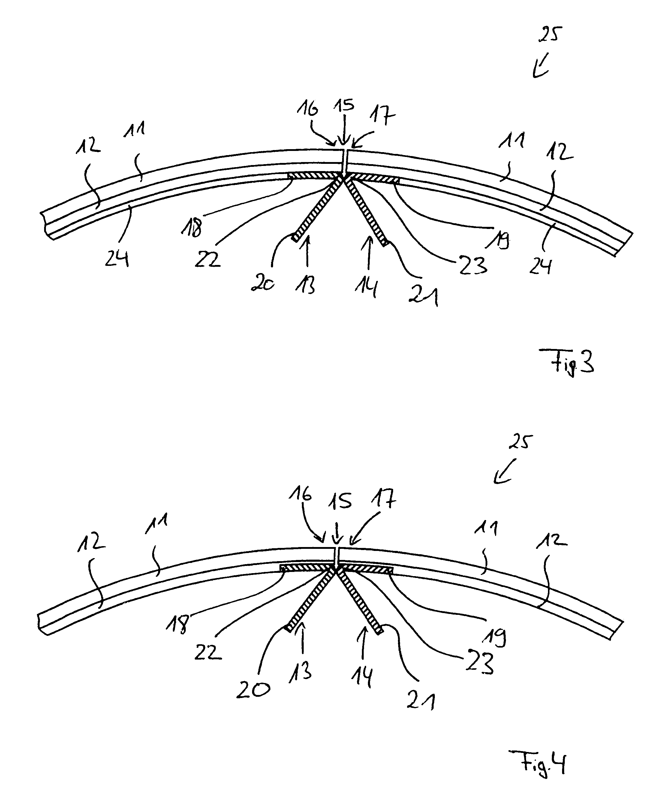
[0019]In the following text, the present invention will be described in greater detail with reference to FIGS. 1 to 7.

[0020]FIG. 1 shows a detail from an ink transfer device 10 according to the invention when the device is clamped on a rubber-covered cylinder, not illustrated, the ink transfer device 10 of FIG. 1 including a rubber blanket 11 and a carrier element 12 assigned to the rubber blanket 11. Rubber blanket 11 and carrier element 12 are designed as separate subassemblies in the exemplary embodiment of FIG. 1.

[0021]The rubber blanket 11 can be formed in a plurality of layers. The carrier element 12 can be designed as a metal carrier, woven fabric carrier or as a fibre-reinforced plastic carrier. According to FIG. 1, in the clamped state, the carrier element 12 is positioned radially on the inside and the rubber blanket 11 radially on the outside. The carrier element 12 is used to hold the rubber blanket 11. It should be pointed out that the carrier element 12 can also be an ...


PUM


Abstract

An ink transfer device which can be clamped on a rubber covered cylinder in a printing press includes a rubber blanket for transferring ink from a printing forme to a printing material, the blanket having a leading end and a trailing end which are separated by a non-ink transferring gap when the device is clamped on the cylinder; a carrier element fixed to the rubber blanket; and a pair of fixing elements for clamping the blanket on the cylinder, the fixing elements being positioned on the carrier adjacent to respective ends of the blanket. In order to minimize the non-ink transferring gap, the fixing elements and the carrier element are formed as separate subassemblies which are joined together.

Description

BACKGROUND OF THE INVENTION[0001]1. Field of the Invention[0002]The invention relates to an ink transfer device which can be clamped on a rubber covered cylinder in a printing press, including a rubber blanket, a carrier element fixed to the rubber blanket, and a pair of fixing elements for clamping the blanket on the cylinder, the fixing elements being positioned on the carrier adjacent to respective ends of the blanket.[0003]2. Description of the Related Art[0004]In the printing units of a printing press, with the aid of what are known as inking units, printing ink is transferred as a function of a subject onto a printing forme positioned on a forme cylinder of the respective printing unit. With the aid of an ink transfer device, the printing ink applied to the printing forme is transferred to a printing material to be printed. Transfer devices known from the prior art are based either on what are known as rubber blankets or on what are known as rubber sleeves.[0005]Rubber sleeves...

Claims


Application Information

Patent Timeline
Patent Type & Authority Patents(United States)
IPC IPC(8): B41F27/12
CPCB41N10/06B41F30/04Y10S428/909
Inventor GRIESER, ALFONSHOFFMANN, EDUARDSCHMID, GEORG
Owner MANROLANAD AG
Why Eureka
Try Eureka