
Self-pumping hydropneumatic spring strut

a hydropneumatic spring and self-pumping technology, which is applied in the direction of shock absorbers, machine supports, transportation and packaging, etc., can solve the problems of unavoidable rocking movement, unfavorable spring characteristic curve production, and inability to produce different spring characteristic curves

Inactive Publication Date: 2009-08-04
ZF FRIEDRICHSHAFEN AG
View PDF7 Cites 8 Cited by
  • Summary
  • Abstract
  • Description
  • Claims
  • Application Information

AI Technical Summary

Benefits of technology

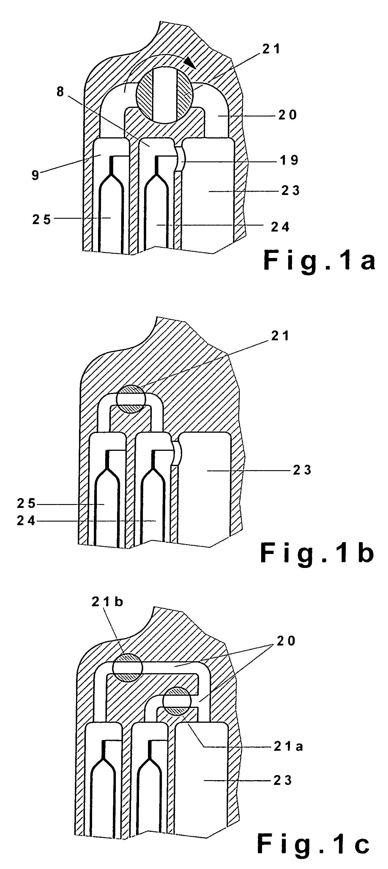
The present invention is about a self-pumping hydropneumatic spring strut with internal level control. It aims to counteract the rocking movement of a vehicle, especially those with tall bodies. The invention uses two parallel high-pressure chambers, which can be briefly disconnected to have no effect on the practical spring action of the strut. This allows for a more stabilizing effect on the vehicle. The spring strut offers two different spring characteristic curves, which can be applied even during operation of the vehicle. By connecting and cutting off one of the two high-pressure chambers, furthermore, it is also possible to stabilize the vehicle against rocking. The invention also provides a shut-off valve and a controllable electronically actuated shut-off valve. The gas cushion is separated from the oil, and the gas cushions of the first and second high-pressure chambers are of different size to obtain various types of spring characteristic curves.

Problems solved by technology

This undesirable rocking movement also occurs to an increased extent in vehicles which have a relatively high center of gravity.
In these vehicles, the problem of rocking is unavoidable.
This design does not make it possible to produce different spring characteristic curves.

Method used


Image

  • Self-pumping hydropneumatic spring strut
  • Self-pumping hydropneumatic spring strut
  • Self-pumping hydropneumatic spring strut

Examples


Embodiment Construction

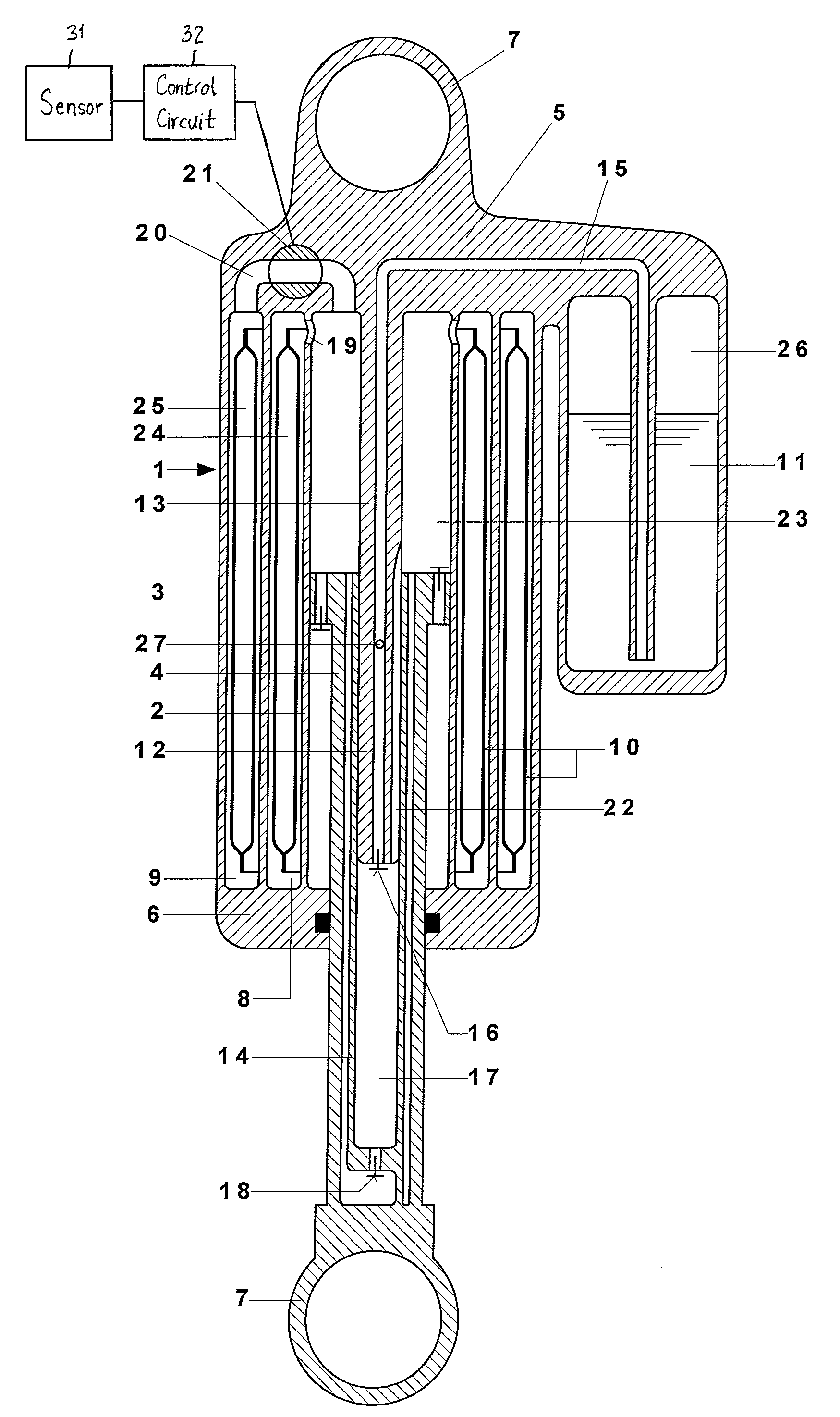
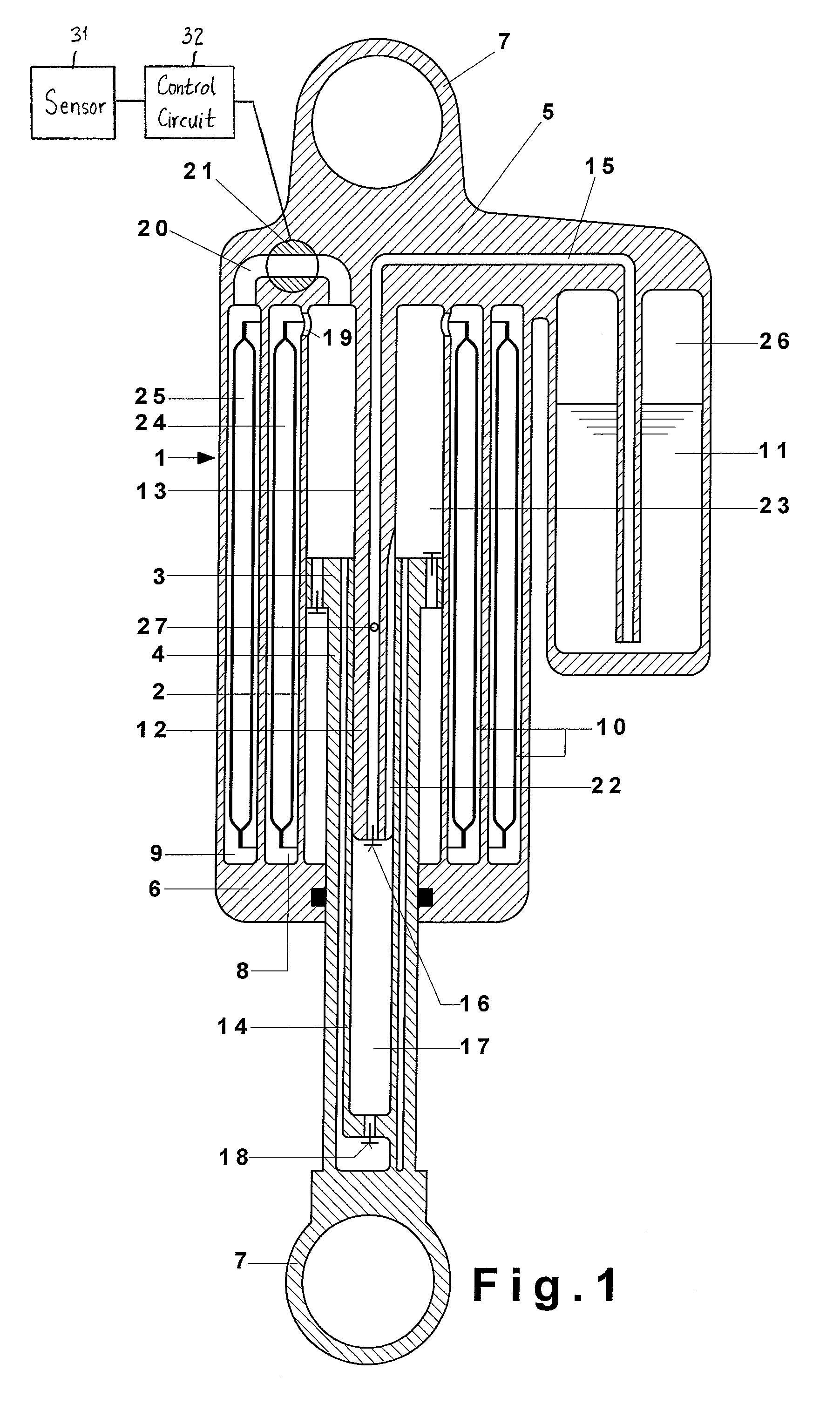
[0021]The self-pumping hydropneumatic spring strut 1 for motor vehicles, which is shown in FIG. 1, consists essentially of the working cylinder 2, in which a piston 3 arranged at the end of a piston rod 4 slides. The working cylinder 2 is closed at one end by a bottom piece 5 and at the other end by a cover, through which the piston rod 4 extends to the outside in a sealed manner through the piston rod guide 6. The bottom piece 5 is attached by means of a first mounting eye 7 to the body of the vehicle (not shown), and the piston rod 4 is attached by means of a second mounting eye 7 to the axle of the vehicle (also not shown).

[0022]The working cylinder 2 is enclosed by two ring-shaped high-pressure chambers 8, 9, which are filled partially with oil and gas. The oil in each chamber 8, 9 is separated from the gas by a separating element 10. In this exemplary embodiment, the gas-tight wall of a gas bag is provided as the separating element 10, but rubber diaphragms, separating pistons,...


PUM


Abstract

A self-pumping hydropneumatic spring strut includes an oil-filled working cylinder which is divided into two working spaces by a working piston carried by a hollow piston rod. Two high-pressure chambers connectable to the cylinder in such that the piston rod is selectively supported in both directions of movement either on a gas cushion provided by the first high-pressure chamber, the second high-pressure chamber, or both high-pressure chambers. Further, the spring strut includes a piston pump driven by the movements of the piston rod and for conveying oil from a low-pressure chamber to the working space which is connected to at least one of the high-pressure chambers. Moreover, a control channel connects the working space, which is connected to at least one of the high-pressure chambers, to the low-pressure chamber via a control opening, which can be closed as a function of the position of the working piston in the working cylinder.

Description

BACKGROUND OF THE INVENTION[0001]The invention pertains to a self-pumping hydropneumatic spring strut with internal level control, in particular used for motor vehicles.[0002]Such spring struts may comprise an oil-filled working cylinder divided into two working spaces by a working piston carried by a hollow piston rod, wherein one working space is connected to a high-pressure chamber and the piston rod is supported against the gas cushion in that high-pressure chamber, which acts as a spring. Further, the spring strut may comprise a piston pump driven by the movements of the piston rod, thus conveying oil from a low-pressure chamber to the working space connected to the high-pressure chamber. The piston pump includes a cylinder formed by the hollow piston rod and a hollow pump rod attached to the working cylinder and carrying a suction valve at its forward end. The pump rod fits into the piston pump cylinder and the bore of the pump rod is connected to the low-pressure chamber. The...

Claims


Application Information

Patent Timeline
Patent Type & Authority Patents(United States)
IPC IPC(8): B60G17/00F16F9/34
CPCF16F9/092F16F9/00F16F9/48B60G15/06
Inventor BECK, HUBERT
Owner ZF FRIEDRICHSHAFEN AG
Learn More