Ultrasonic endoscope

a technology of endoscope and ultrasonic technology, applied in the field of ultrasonic endoscope, can solve the problems of large burden on subjects, deformation of the operationity of the distal hard portion to be inserted into the body cavity, and increase the outside diameter of the distal hard portion, so as to reduce the thickness of the backing layer and widen the fitting space

Inactive Publication Date: 2009-08-04
FUJI PHOTO OPTICAL CO LTD
View PDF13 Cites 57 Cited by
  • Summary
  • Abstract
  • Description
  • Claims
  • Application Information

AI Technical Summary

Benefits of technology

[0018]Part of the members constituting the endoscopic observation means are changed in cross-sectional shape in the axial direction in a portion located in the distal hard portion. For example, an illumination lens constituting an illumination section is larger in diameter than a light guide constituting the same. In an observation section, an objective lens, because it is made of a plurality of lenses, is fitted in a lens barrel, and the cross-sectional shape of the lens barrel is circular, but a solid-state image pickup device arranged at an image-forming position of the objective lens is planar and is mounted on a circuit board. In addition, signal cables are led from the circuit board. Therefore, the lens barrel differs in shape and dimension from members arranged on a proximal side from the lens barrel. For this reason, the distal block is extended forwardly from an area in which the tunnel-shaped path is formed in the ultrasonic observation means. Accordingly, the outside diameter of the distal block can be made approximately the same as the outside diameter of the ultrasonic observation means. In addition, as mentioned above, a section whose distal end is protruded toward the outer circumferential side from a section located in the inside of the tunnel-shaped path is provided in the distal block enlarged in diameter in the above-mentioned manner. Accordingly, the dependency of the endoscopic observation means on the tunnel-shaped path can be solved, and even if each of the members is given a size which allows them to effectively perform their functions, the distal hard portion does not become thick in diameter. In addition, the distal block can be constructed of an endoscope fitting member formed of a metallic material in terms of strength and workability, and a distal cap made of an insulative member fitted so as to prevent the endoscope fitting member from being exposed to the outside, so that the members constituting the endoscopic observation means can be fixed to the distal block. At at least a position where the distal cap is fitted, the illumination section or the observation section is increased in diameter so as to be partially protruded from the inside diameter of the tunnel-shaped path. In the illumination section in particular, a section inserted in the tunnel-shaped path can be arbitrarily deformed in cross section, so that the section inserted can be, for example, bypassed so as not to interfere with other members.
[0022]By adopting the above-mentioned construction, it is possible to arrange any of the members constituting the endoscopic observation means on the outer circumferential side from the tunnel-shaped path without allowing any of the members to interfere with the ultrasonic observation means, whereby it is possible to provide the advantage of thinning the diameter of the distal hard portion of the insertion portion.
[0026]According to the above-described construction, since a joining section between distal and proximal members is not exposed to the outside in any area from the angle portion constituting the insertion portion to the distal hard portion, it is possible to achieve the advantage of increasing the airtightness of the inside of the ultrasonic endoscope.
[0029]Accordingly, since the filler can serve a function similar to the backing layer, it is possible to reduce the thickness of the backing layer which constitutes the ultrasonic observation means, and it is possible to achieve advantages such as widening the fitting space for the endoscopic mechanism by the corresponding amount.

Problems solved by technology

Accordingly, if the sizes of the respective members constituting the ultrasonic observation means and the endoscopic observation means are made equivalent to dimensions necessary for their respective functions, the outside diameter of the distal hard portion increases and the operationality with which the distal hard portion is to be inserted into a body cavity is not only degraded, but also a large burden is imposed on a subject.
This degradation causes problems such as lowering of seal functions of the adhesion sections.
As described above, the ultrasonic endoscope has the problem that if any of the functions of the ultrasonic observation means or the endoscopic mechanism is to be improved, the insertion portion must be made thick as needed.

Method used


Image

  • Ultrasonic endoscope
  • Ultrasonic endoscope
  • Ultrasonic endoscope

Examples


first embodiment

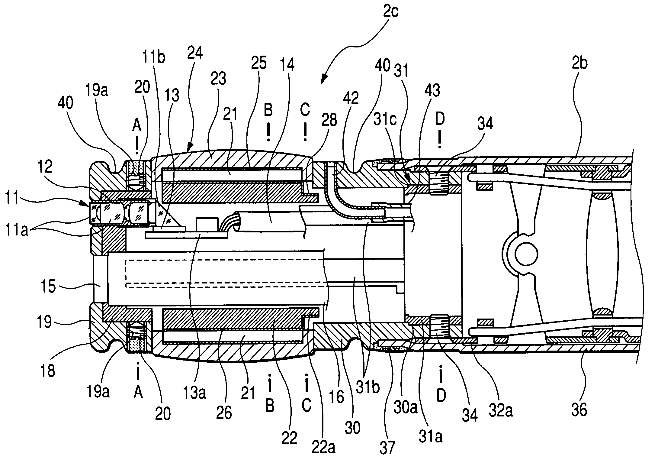
[0058]In the distal end of the insertion portion 2 (FIGS. 4A, 5A, 6A, 7A and 8A), each of the ultrasonic transducers 21 has two electrode 25 and 26, and the electrode 25 is a common electrode 25 common to all (or each predetermined number of) the ultrasonic transducers 21. The electrodes 26 are individually provided for the respective ultrasonic transducers 21. The common electrode 25 and the individual electrodes 26 of the ultrasonic transducers 21 are electrically connected to terminal sections of wiring patterns formed on a film substrate. As shown in FIG. 7A, a film substrate 28 is connected between the individual electrodes 26 of the respective ultrasonic transducers 21 and a predetermined number of cables 27 so that the cables 27 are respectively connected to the individual electrodes 26. In principle, the electrode 25 may be connected to one cable, and although not shown, the one cable is connected on the distal side of the ultrasonic transducers 21. A reduced-diameter sectio...

second embodiment

[0060]In the distal end of the insertion portion 2 (FIGS. 4B, 5B, 6B, 7B and 8B), each of the ultrasonic transducers 21 has electrodes formed on its obverse and reverse sides, and a flexible circuit board 124 abuts on the reverse side, i.e., on a side where the ultrasonic transducers 21 are fitted to the backing layer 22, and a predetermined wiring pattern is formed on the flexible circuit board 124. A multiplicity of cables 125 are connected to the flexible circuit board 124, and each of the cables 125 is extended toward the proximal side of the insertion portion 2. Accordingly, the respective electrodes on the reverse sides of the ultrasonic transducers 21 are individual electrodes. In general, the number of the cables 125 is made equal to the number of the ultrasonic transducers 21 which constitute the ultrasonic transducer array 123, but the number of the cables 125 can also be reduced by short-circuiting lines from a plurality of ones of the ultrasonic transducers 21 on the fle...


PUM


Abstract

An ultrasonic endoscope comprises an insertion portion comprising a distal hard portion which has: an endoscopic observation unit; and an ultrasonic observation unit having ultrasonic transducers arranged circumferentially on an outer circumferential section of the distal hard portion, wherein the ultrasonic observation unit comprises an ultrasonic-wave transmission / reception unit having an tunnel-shaped path which has an inner circumferential surface formed as a backing layer; a distal block is arranged on a distal side in an axial direction of the distal hard portion with respect to a location where the ultrasonic-wave transmission / reception unit is arranged, and distal ends of respective members constituting the endoscopic observation unit are fixed to the distal block; and part of the members which constitute the endoscopic observation unit are fitted so as to be partially protruded from an inside diameter of the tunnel-shaped path toward an outer circumferential side thereof.

Description

BACKGROUND OF THE INVENTION[0001]1. Field of the Invention[0002]The present invention relates to an ultrasonic endoscope whose insertion portion includes a distal hard portion which has an endoscopic observation unit having an observation field of view forwardly of the endoscopic observation unit, and an electronic scanning type of an ultrasonic observation unit having a circular or arcuate ultrasonic scanning plane perpendicular to the axis of the distal hard portion.[0003]2. Description of the Related Art[0004]A so-called electronic scanning type of ultrasonic endoscope has heretofore been widely used in which endoscopic observation means for observing a body cavity, an endoscopic mechanism including other means such as a treatment equipment insertion path through which to insert forceps or other treatment equipments, and ultrasonic observation means are fitted in a distal hard portion of an insertion portion and the ultrasonic observation means performs scanning by sequentially d...

Claims


Application Information

Patent Timeline
Patent Type & Authority Patents(United States)
IPC IPC(8): A61B1/06A61B1/04A61B8/12
CPCA61B1/00096A61B1/018A61B8/445A61B8/4488A61B8/12
Inventor TANAKA, TOSHIZUMIITOI, HIROMU
Owner FUJI PHOTO OPTICAL CO LTD
Why Eureka
Try Eureka