Disk drive suspension with reduced off-track error

a technology of suspension and disc drive, applied in the direction of magnetic recording, data recording, instruments, etc., can solve the problems of unsatisfactory and undesirable '508 patent approach, less rigid mounting plate, etc., to reduce the force displacement, minimize errors, and reduce limitations and errors. fewer and less severe

Active Publication Date: 2009-08-04
MAGNECOMP
View PDF8 Cites 8 Cited by
  • Summary
  • Abstract
  • Description
  • Claims
  • Application Information

AI Technical Summary

Benefits of technology

[0017]It is an object of the present invention to provide an improved disk drive having fewer and less severe limitations and errors. It is a further object to provide a suspension and actuator combination for a disk drive suspension for such an improved disk drive. It is a further object to provide a novel arrangement of suspension components that minimizes errors. It is a particular object to achieve minimization of errors through a reduction in the force displacement of error-generating motions. It is another object to provide a disk drive suspension in which applied force from the actuator through the suspension to the slider and the slider center of mass are substantially coincident and not spaced to thus minimize torque applied to the slider. A still further object is to provide such a disk drive suspension in which the center of curvature of the dimple and the horizontal plane containing the slider gap are substantially coincident so as to minimize lateral gap displacement during suspension torsional vibration. An additional object is to provide disk drive suspension in which the off track lateral displacement motions, and therefore TMR errors due to torsional and sway vibrations, are reduced, thus minimizing drive performance degradations from seek and windage sources. A further object is to provide a mounting plate that has angled parts to direct the suspension beam portion along a suspension datum plane that diverges from the mounting datum plane, the base part being free of strain concentrating openings or holes, in contrast to U.S. Pat. No. 6,063,508, for example where the base part of the mounting plate is intentionally apertured to enable part distortion for gram adjustment at the mounting plate. This practice, however, makes the mounting plate less rigid, an undesirable result since mounting plate rigidity is essential for optimum suspension resonance, shock and uniformity of performance (reduced sigma). The availability of better techniques for making gram adjustments, such as laser heating of the hinge region, makes the '508 patent approach unnecessary as well as undesirable.

Problems solved by technology

This practice, however, makes the mounting plate less rigid, an undesirable result since mounting plate rigidity is essential for optimum suspension resonance, shock and uniformity of performance (reduced sigma).
The availability of better techniques for making gram adjustments, such as laser heating of the hinge region, makes the '508 patent approach unnecessary as well as undesirable.

Method used


Image

  • Disk drive suspension with reduced off-track error
  • Disk drive suspension with reduced off-track error
  • Disk drive suspension with reduced off-track error

Examples


Embodiment Construction

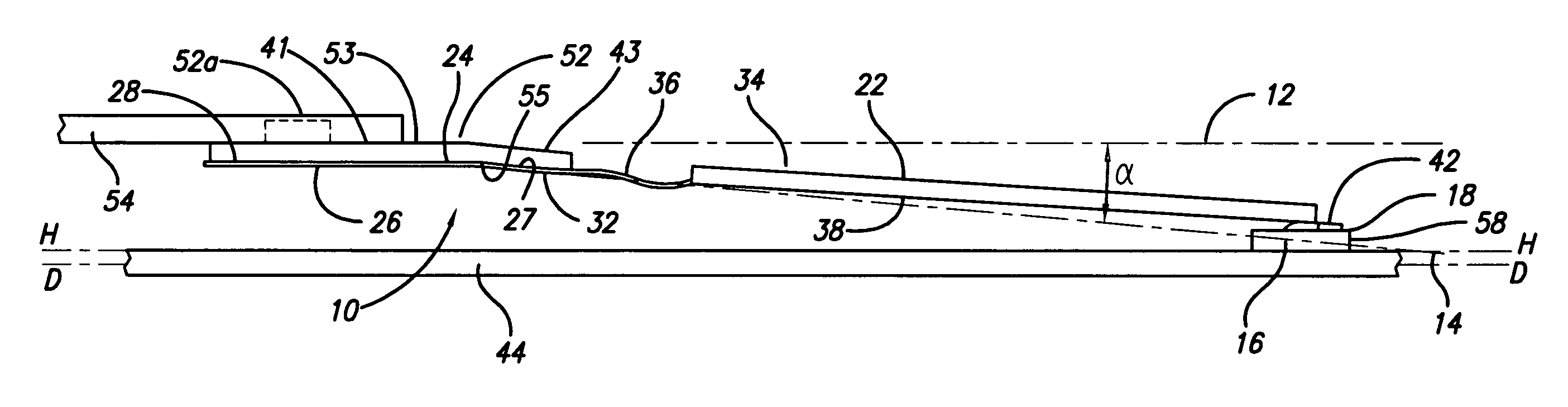
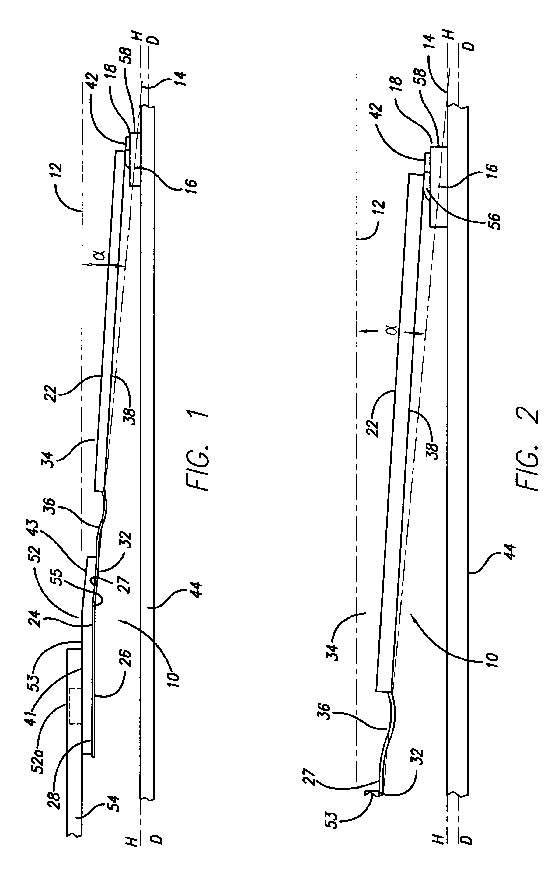
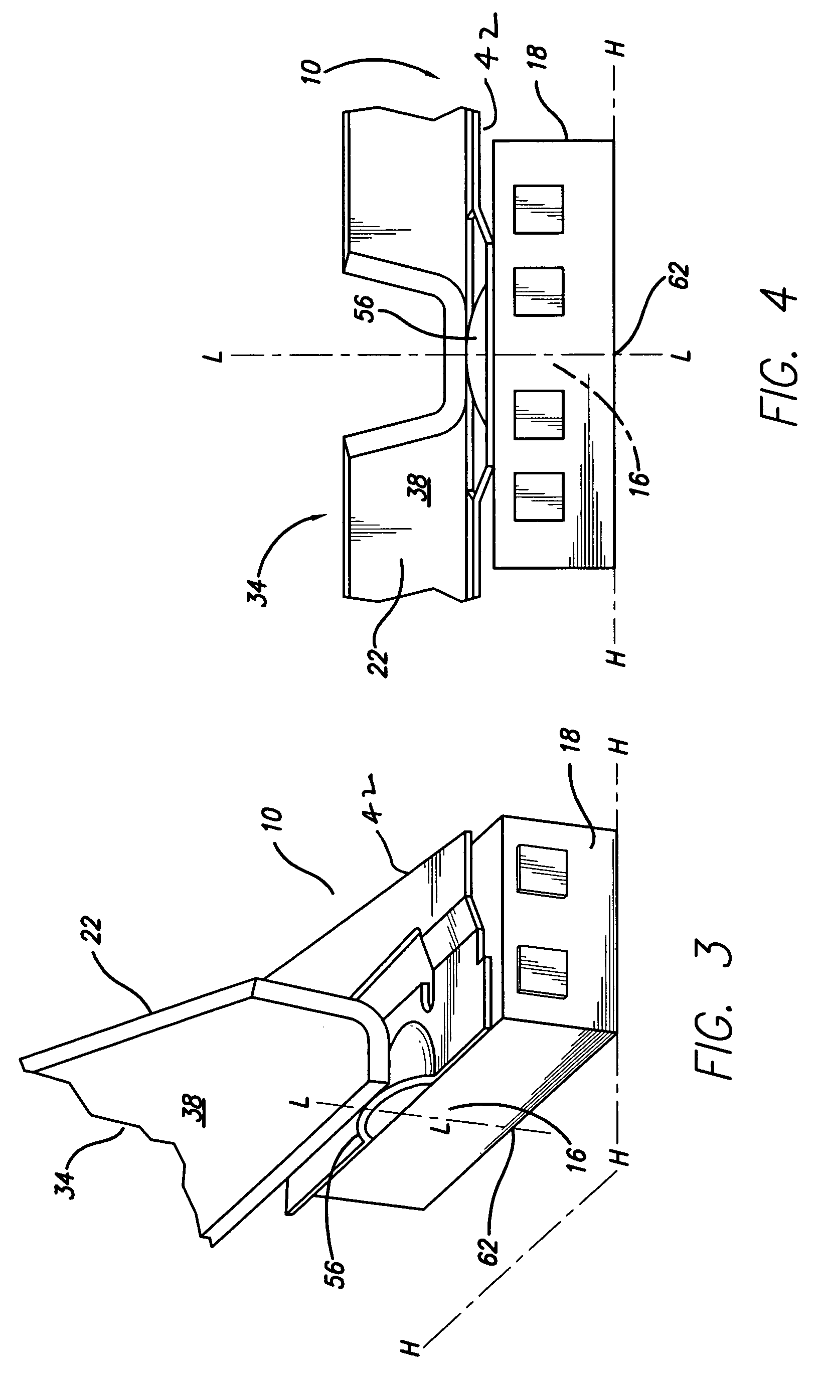
[0082]With reference now to the drawings in detail, in FIGS. 1-7B, disk drive suspension 10 has its mounting datum plane 12 and its suspension datum plane 14 diverge so that the suspension datum plane extends through the center of mass 16 of the slider 18. Suspension 10 comprises a load beam 22 having a proximate region 24 comprising a base portion 26 typically having a first part 28 extending in or parallel with the mounting datum plane 12 and a second part 32 extending in the suspension datum plane 14 at an angle α to the mounting datum plane. Base portion 26 is shown attached to the lower surface 55 of mounting plate 52, but can alternatively be attached to the top surface 53 thereof. Suspension 10 has a distal region 34 comprising a hinge portion 36 and a beam portion 38, a flexure 42 carried by the suspension distal region and supporting slider 18 in gimballing relation with the beam portion for operative association of the slider with a disk 44. Suspension datum plane 14 exten...


PUM

PropertyMeasurementUnit
angleaaaaaaaaaa
angleaaaaaaaaaa
heightaaaaaaaaaa

Abstract

Apparatus for a disk drive having an actuator controlled suspension in operative association with a disk. The suspension mounting plane datum plane and suspension datum plane diverge at an acute angle. When the suspension is subjected to use conditions including seek operations and disk-induced turbulent wind flow conditions and induce sway forces and torsion forces that produce lateral off-track motions of the slider gap, the extension of the suspension datum plane substantially through the slider center of mass minimizes sway forces, and lateral off track motion of the slider gap is minimized. Error from torsion forces is minimized by having the dimple center of curvature coincide with a horizontal plane including the slider gap and having the dimple longitudinal axis extend through the slider center of mass, so that both sway and torsion force sources of track misregistration are addressed.

Description

CROSS-REFERENCE TO RELATED APPLICATIONS[0001]This application claims the benefit of U.S. Provisional Application Ser. No. 60 / 666,514, filed Mar. 29, 2005.STATEMENT REGARDING FEDERALLY SPONSORED RESEARCH OR DEVELOPMENT[0002]Not ApplicableREFERENCE TO A MICROFICHE APPENDIX[0003]Not ApplicableBACKGROUND OF THE INVENTION[0004]1. Field of the Invention[0005]This invention relates to improvements in the design and use of disk drive suspensions to reduce to near extinction disk drive off-track errors, e.g. track misregistration errors (TMR), that have proved irremediable by conventional disk drive design and manufacturing execution.[0006]Off-track motion, generally, and TMR specifically, herein refer to unwanted variances in the position and attitude of the slider gap from that desired. A slider is an aerodynamic body that carries a magnetic head in operating proximity to a rotating disk A slider gap is the space between the pole pieces of the slider-carried magnetic head. As part of a mag...

Claims


Application Information

Patent Timeline
Patent Type & Authority Patents(United States)
IPC IPC(8): G11B5/48G11B21/16
CPCG11B5/4826
Inventor COON, WARREN
Owner MAGNECOMP
Why Eureka
Try Eureka