Image forming apparatus having heat-fixing unit

a technology of heat fixing unit and image forming apparatus, which is applied in the direction of electrographic process apparatus, instruments, optics, etc., can solve the problems of deterioration of the discharge performance of recording material of small size and inability to ensure proper discharge performance, so as to suppress the occurrence of defective images and ensure the discharge performance of recording materials

Inactive Publication Date: 2009-08-04
CANON KK
View PDF10 Cites 21 Cited by
  • Summary
  • Abstract
  • Description
  • Claims
  • Application Information

AI Technical Summary

Benefits of technology

[0013]The invention is made in consideration of the foregoing problems and it is an object of the invention to provide an image forming apparatus which can assure discharge performance of a recording material while suppressing the occurrence of a defective image.
[0014]Another object of the invention is to provide an image forming apparatus which can assure discharge performance of a recording material of a small size while suppressing the occurrence of a defective image.

Problems solved by technology

However, in the case of printing onto a recording material of a small size by a printer in which the non-divided roller having the projecting portions only in both edge portions in the axial direction is used as a roller of the discharge portion, since the recording material cannot be pushed out by the projecting portions, there is a possibility of deterioration of the discharge performance of the recording material of the small size.
Particularly, in the case of printing onto the recording material of the small size, since control for decreasing a fixing speed is made to suppress over-rising of a temperature in an area of the fixing portion where the recording material does not pass, such a situation that the proper discharge performance cannot be assured is considered.

Method used


Image

  • Image forming apparatus having heat-fixing unit
  • Image forming apparatus having heat-fixing unit
  • Image forming apparatus having heat-fixing unit

Examples


embodiment 1

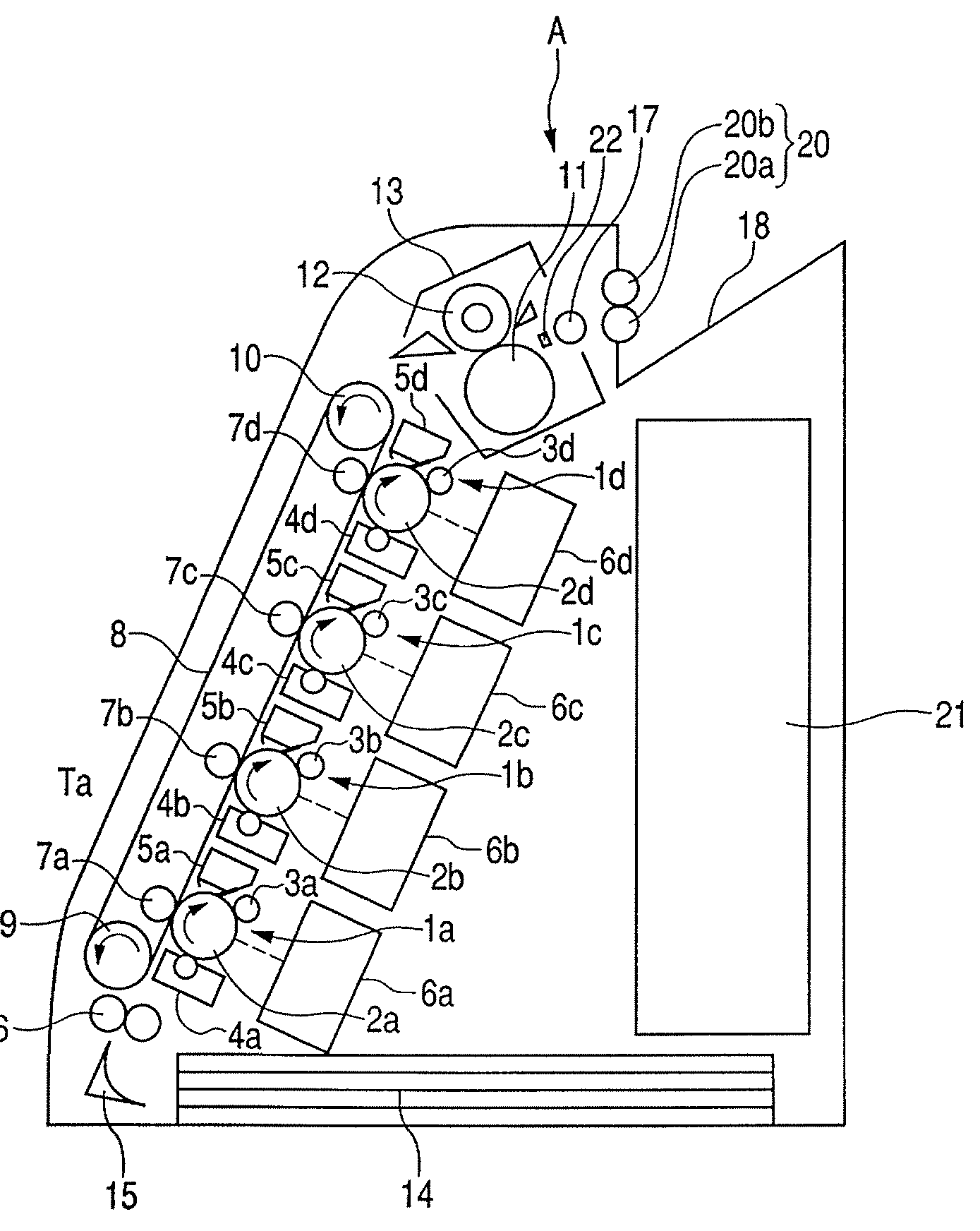
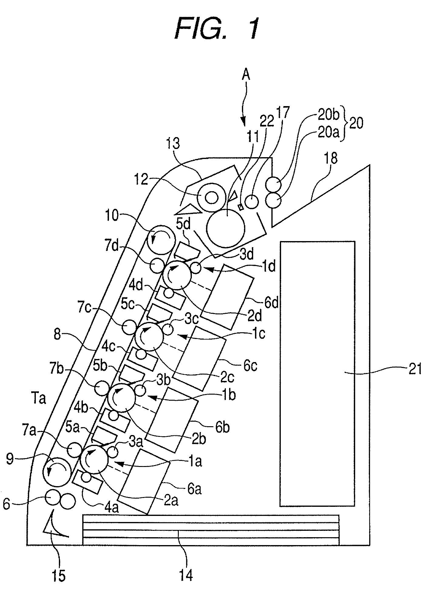
[0028]FIG. 1 is a schematic cross sectional view of an image forming apparatus A in an embodiment 1 of the invention. The image forming apparatus A according to the embodiment is a color image forming apparatus using an electrophotographic image forming process.

[0029]The image forming apparatus A has the following four image forming portions: an image forming portion 1a for forming a yellow image; an image forming portion 1b for forming a magenta image; an image forming portion 1c for forming a cyan image; and an image forming portion 1d for forming a black image. The four image forming portions 1a, 1b, 1c, and 1d (hereinbelow, also referred to as 1a to 1d) are arranged in a line at predetermined intervals.

[0030]Drum type electrophotographic photosensitive materials (hereinbelow, referred to as photosensitive drums) 2a, 2b, 2c, and 2d (hereinbelow, also referred to as 2a to 2d) as image bearing members are arranged in the image forming portions 1a, 1b, 1c, and 1d, respectively. Char...

embodiment 2

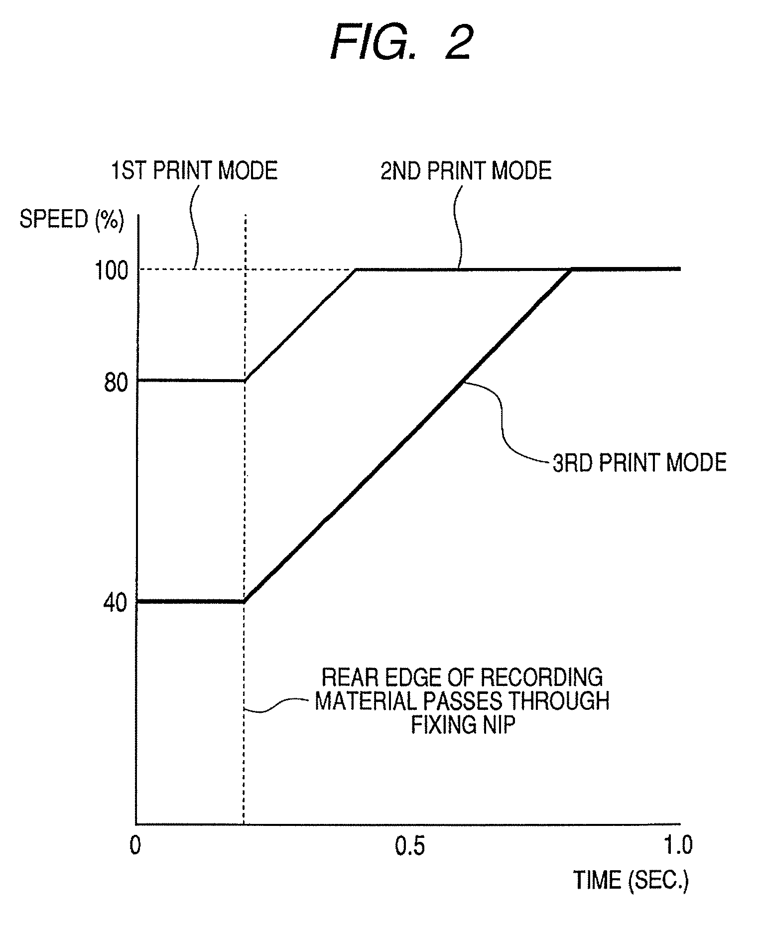
[0088]An image forming apparatus according to an embodiment 2 of the invention differs from the image forming apparatus A according to the embodiment 1 mentioned above with respect to a point that control is made so as to gradually raise the speed when the conveying speed of the fixing portion and the discharge portion is switched after the recording material passed through the fixing nip portion. FIG. 2 is a diagram for describing a speed increasing method in the embodiment 2.

[0089]If the speed is suddenly switched, there is a fear that the recording material is hooked to the discharge tray due to a shock of the speed switching and a rounding phenomenon of the recording material occurs therefrom as a start point.

[0090]In the image forming apparatus of the embodiment, as illustrated in FIG. 2, the control unit 21 continuously changes the speed of the fixing apparatus 13 and the discharge roller pair 20 at a speed increasing rate of 10% of the speed in the first print mode per about ...


PUM


Abstract

An image forming apparatus includes an image forming portion; a fixing portion having a fixing nip portion which heats and fixes the unfixed image and an discharge roller which discharges the recording material, wherein in the case where the recording material is the plain paper which is equal to or larger than the predetermined size, the discharge roller conveys the plain paper in a range from a front edge to a rear edge at a predetermined speed, in the case where the recording material is the plain paper smaller than the predetermined size, the discharge roller conveys the plain paper at a first speed until the rear edge passes through the fixing nip portion, and the discharge roller conveys the plain paper at a second speed higher than the first speed after the rear edge passed through the fixing nip portion.

Description

BACKGROUND OF THE INVENTION[0001]1. Field of the Invention[0002]The present invention relates to an image forming apparatus such as copying apparatus, printer, or the like and, more particularly, to an image forming apparatus in which a heat-fixing unit has been provided.[0003]2. Description of the Related Art[0004]An image forming apparatus of an electrophotographic recording system forms a toner image onto a recording material, thereafter, executes a heat-fixing process to the toner image, and discharges the recording material onto a discharge tray. A schematic construction of a laser beam printer (LBP) as an example of such an image forming apparatus will now be described with reference to FIG. 3. The LBP illustrated in FIG. 3 is a printer for forming a monochromatic image.[0005]In the diagram, a processing unit 101 including a photosensitive drum 102 is arranged in a main body of the image forming apparatus. A laser beam modulated according to image information is irradiated ont...

Claims


Application Information

Patent Timeline
Patent Type & Authority Patents(United States)
IPC IPC(8): G03G15/20
CPCG03G15/6573G03G15/2028G03G2215/00945G03G2215/00734
Inventor ANDO, ATSUTOSHIOBARA, YUUICHISAHARA, HIROSHI
Owner CANON KK
Why Eureka
Try Eureka