Tape reel, recording tape cartridge, take-up reel, drawing-out member, and drive device

a technology which is applied in the field of drive device and recording tape cartridge, can solve the problems of generating recording/reproducing error of data signal, damaging tape edge, and displacement, and achieves the suppression of one-layer sticking out and distortion of wound recording tape, reducing read error of servo signal, and reducing displacement

Active Publication Date: 2009-08-11
FUJIFILM CORP
View PDF13 Cites 11 Cited by
  • Summary
  • Abstract
  • Description
  • Claims
  • Application Information

AI Technical Summary

Benefits of technology

[0015]In consideration of the above circumstances, the present invention provides a tape reel that, when a recording tape is wound on a hub: enables suppression of displacement in the hub axial direction of the recording tape; enables suppression of one-layer sticking out and distortion of the wound recording tape; enables a reduction in the occurrence of problems due to tape edge folding over and tape edge damage due to recording tape of one-layer that is sticking out contacting a flange when impacted, such as when dropped; and also enables a reduction in read error of a servo signal and recording / reproducing error of a data signal. A recording tape cartridge, take-up reel, drawing-out member, and drive device of the same are also provided.Means by Which the Problem(s) is Solved

Problems solved by technology

For such distorted winding, the recording / reproducing head, moving in the up-down direction on the basis of the servo signal, which has been recorded in advance to the recording tape, is unable to follow the sudden displacements of the recording tape, particularly when fluctuations occur within small intervals of time (at high speed), and it becomes impossible to carry out the desired data signal recording / reproducing.
Namely, in a high recording density recording / reproducing system, the size of the recording signal is becoming finer, recording density is increasing, the size of the servo signal is decreasing, the recording density of the servo signal itself is increasing, servo tracking control methods are controlling at high frequencies, recording tape running speeds are increasing, and fluctuations in the recording tape of a level which previously would not have been a problem are now generating recording / reproducing errors of the data signal due to read errors of the servo signal.
Moreover, when the amount of recording tape curvature is large, sometimes the recording tape deviates too much toward one of the flanges and the tape edge is pressed hard against the flange, damaging the tape edge.
This particularly becomes a significant problem as the recording tape gets thinner.
Furthermore, sometimes if the recording tape is pressed too hard by one of the flanges, the reaction to such pressing leads to the occurrence of one-layer sticking out.
However, the gradual decrease in the upper and lower flange separation due to hub distortion depends on the rigidity of the hub.
Due to this, such a reel may, however, actually worsen the recording tape winding straightness, and / or contribute to tape edge damage.

Method used


Image

  • Tape reel, recording tape cartridge, take-up reel, drawing-out member, and drive device
  • Tape reel, recording tape cartridge, take-up reel, drawing-out member, and drive device
  • Tape reel, recording tape cartridge, take-up reel, drawing-out member, and drive device

Examples


Embodiment Construction

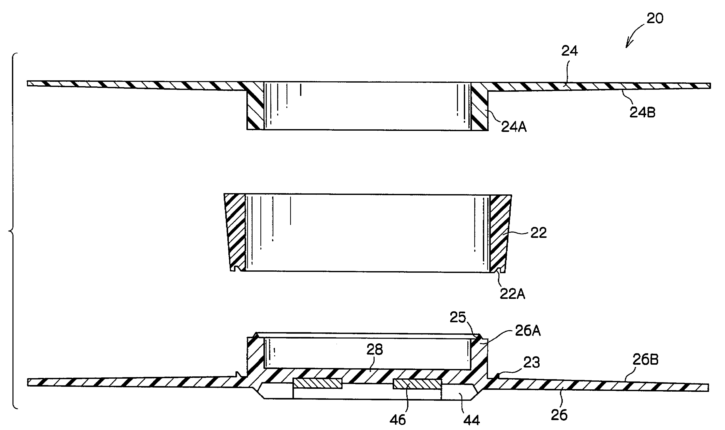
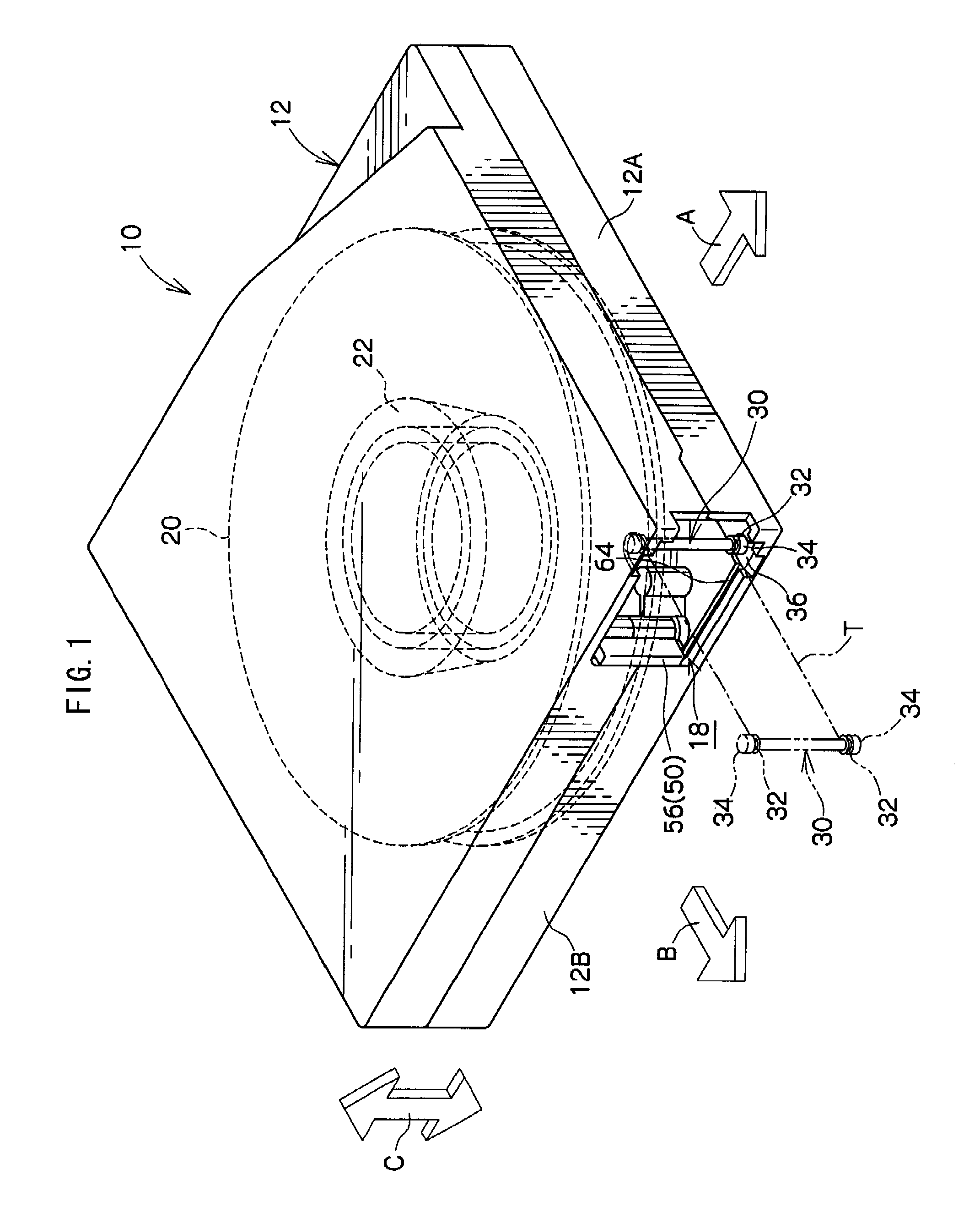
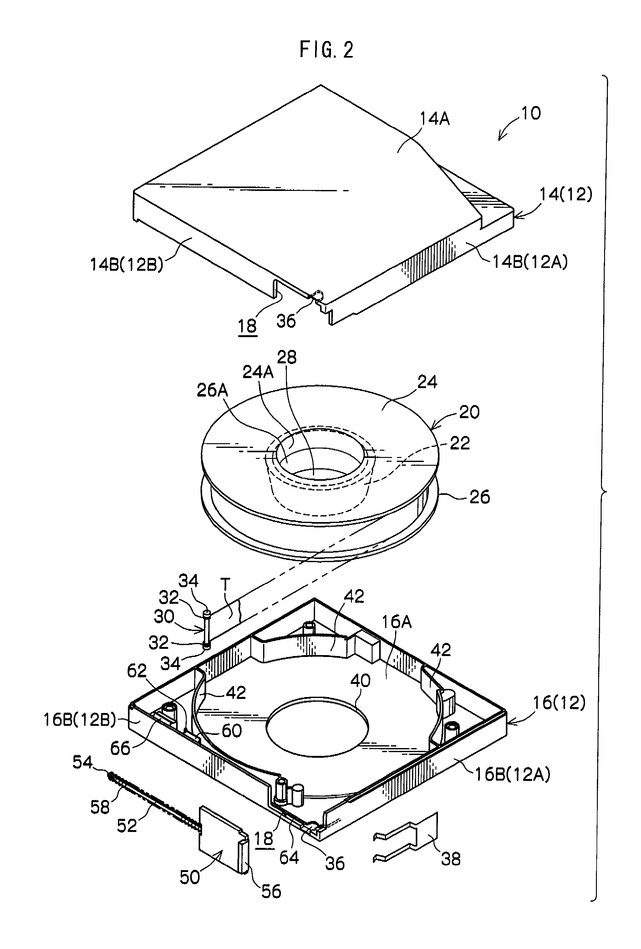
[0106]Explanation will now be given of details of an embodiment of the best mode of the present invention, with reference to an exemplary embodiment shown in the diagrams. It should be noted that, for ease of explanation, in FIG. 1, the direction of loading into a drive device 70 (see FIG. 5) of a recording tape cartridge 10 is shown by the arrow A, and this is designated as the front direction (front side) of the recording tape cartridge 10. Also, the direction orthogonal to the direction of arrow A, shown by the arrow B, is designated as the right direction (right side) of the recording tape cartridge 10. Furthermore, the direction of arrow C is designated as the width direction, and this is the same direction as the up-down direction, and height direction in the present exemplary embodiment, and also the same direction as the axial direction of the reel 20 (reel hub 22), and axial direction of the take-up reel 80 (reel hub 82).

[0107]As shown in FIGS. 1 and 2, the recording tape c...


PUM

PropertyMeasurementUnit
widthaaaaaaaaaa
widthaaaaaaaaaa
thicknessaaaaaaaaaa

Abstract

A tape reel including: a substantially circular cylinder shaped hub; flanges provided as separate bodies from the hub at both end portions of the hub; a connecting member connecting together the flanges at the inside of the hub, in a non-contact state with the inner peripheral face of the hub. The recording tape is wound on the hub in such a manner that the side of the recording tape with the smaller radius of tape edge curvature is on the smaller diameter side of the hub. Also disclosed are: a recording tape cartridge housing such a tape reel; a take-up reel provided in a drive device; a drawing-out member, housed in the hub of a take-up reel and on which recording tape drawn-out from a recording tape cartridge is wound; and a drive device with take-up reel and drawing-out member.

Description

CROSS-REFERENCE TO RELATED APPLICATION[0001]This application claims priority under 35 USC 119 from Japanese Patent Application No. 2007-119573 filed Apr. 27, 2007, the disclosure of which is incorporated by reference herein.BACKGROUND OF THE INVENTION[0002]1. Technical Field[0003]The present invention relates to: a tape reel and a take-up reel, for winding recording tape thereon, such as magnetic tape, which is mainly used as a computer recording and reproduction medium; a recording tape cartridge with tape reel stored within a case; a drawing-out member for pulling out recording tape from a tape reel within a case; and a drive device for mounting a recording tape cartridge.[0004]2. Related Art[0005]Conventionally, recording tape cartridges are known for winding recording tape, such as magnetic tape, used as a data recording / reproducing medium for computers and the like, onto a single reel stored in a case. These recording tape cartridges are, for example, mounted in a drive device,...

Claims


Application Information

Patent Timeline
Patent Type & Authority Patents(United States)
IPC IPC(8): G11B23/107
CPCG11B23/107
Inventor SHIGA, HIDEAKI
Owner FUJIFILM CORP
Why Eureka
Try Eureka