Narrow-angle directional microphone

Inactive Publication Date: 2013-03-14
AUDIO-TECHNICA
View PDF0 Cites 10 Cited by
  • Summary
  • Abstract
  • Description
  • Claims
  • Application Information

AI Technical Summary

Benefits of technology

[0018]In a case where the metallic mesh is provided in this way, in assembling, when inserting the metallic mesh fixed to the acoustic tube into the microphone case, it is easy for the inner circumferential surface of the microphone case and the outer surface of the metallic mesh to slide and thus it can make assembling easy.
[0019]In addition, since the metallic mesh is located at the opening of the microphone case, it is possible to block static electricity and prevent external noise to the inside of the microp

Problems solved by technology

However, there is a problem that when the openings 51 provided in the circumferential wall are especially large, since it is easy for the acoustic resistor 52 to make vibration, the acoustic resistor 52 makes vibration due to a sound wave with a lar

Method used


Image

  • Narrow-angle directional microphone
  • Narrow-angle directional microphone
  • Narrow-angle directional microphone

Examples


Embodiment Construction

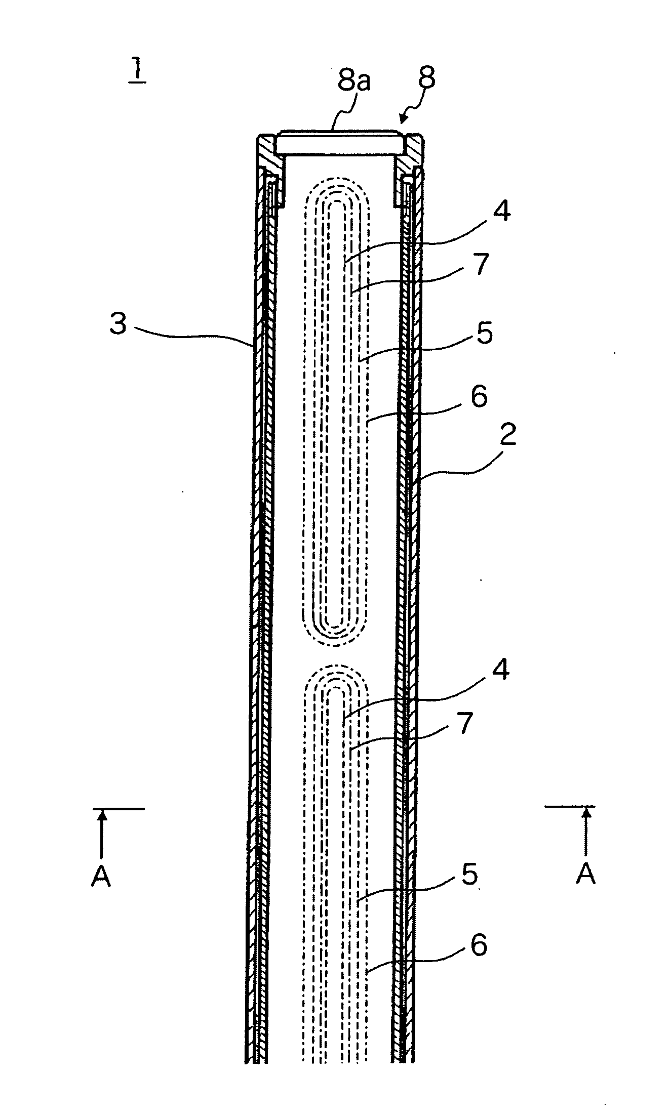
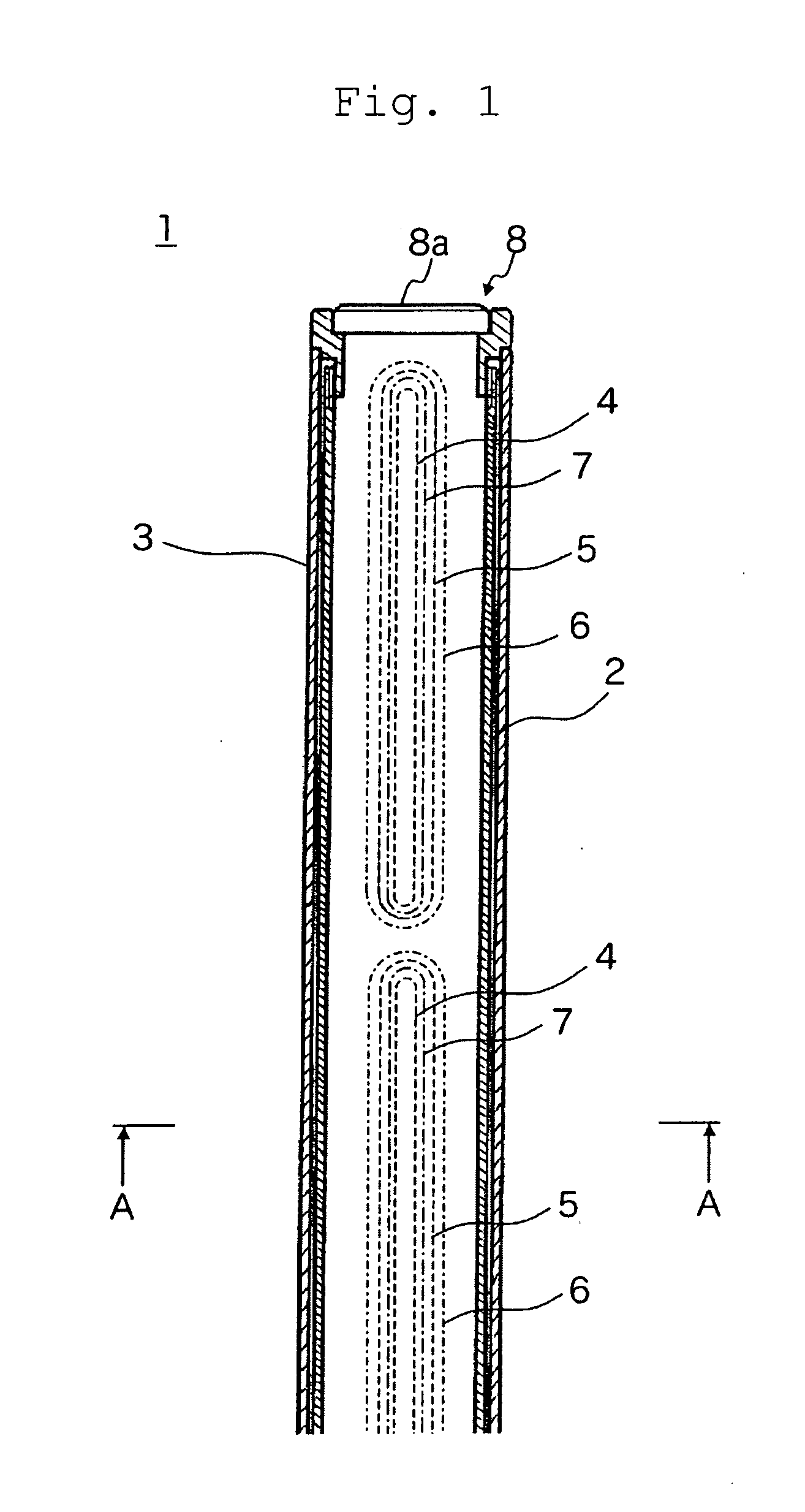
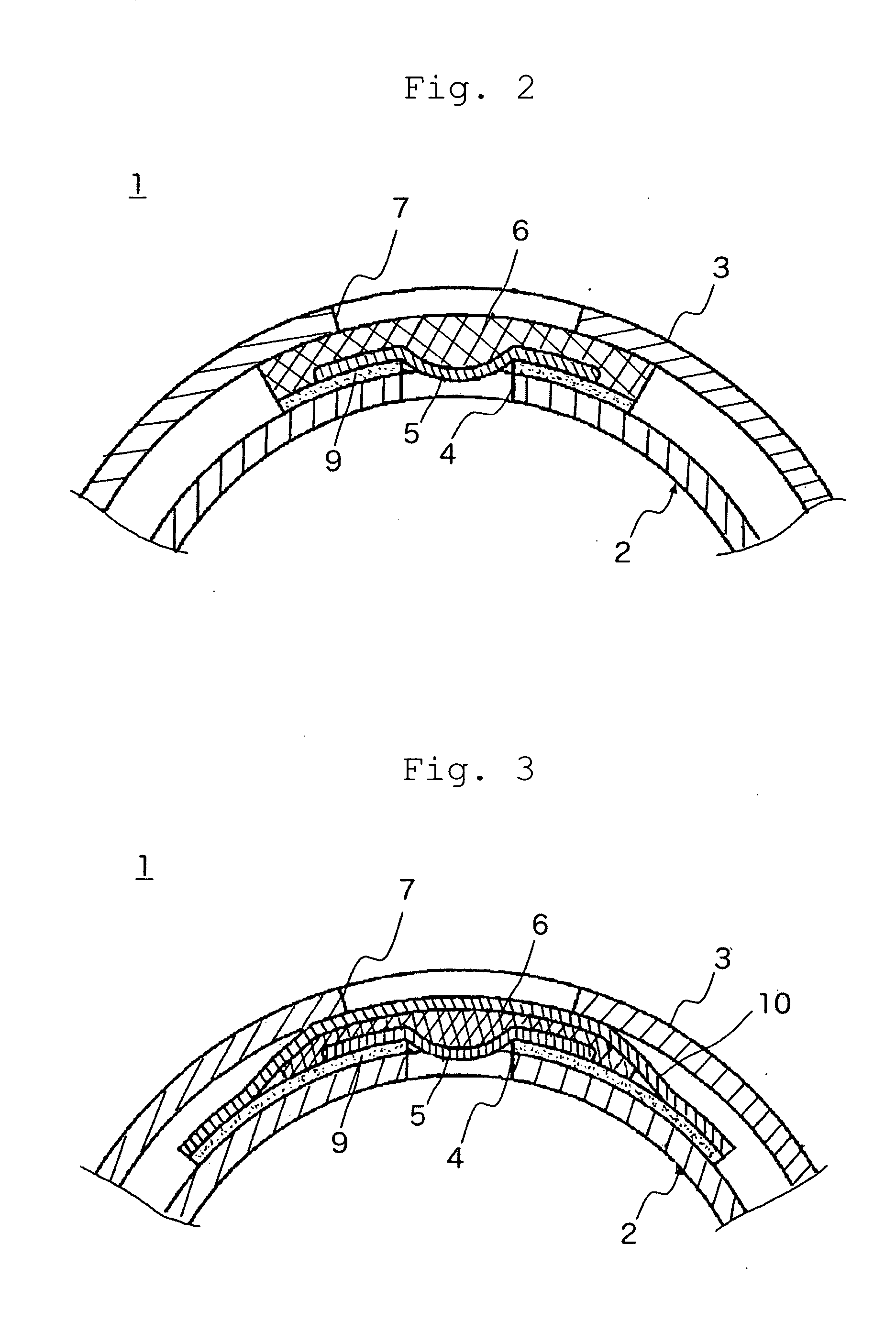
[0027]Hereinafter, embodiments of the invention will be described with reference to the accompanying drawings. FIG. 1 illustrates a narrow-angle directional microphone according to a first embodiment of the invention and is a front cross-sectional view of main components thereof. In addition, FIG. 2 is a cross-sectional view taken along the line A-A (cross-sectional view in the radial direction) of FIG. 1 and illustrates an enlarged part thereof (only the front side of FIG. 1).

[0028]A narrow-angle directional microphone 1 illustrated in FIG. 1 includes a cylindrical acoustic tube 2, to the rear end of which a microphone unit (not illustrated) is attached, and a cylindrical microphone case 3, which accommodates at least the acoustic tube 2 (the microphone unit may also be accommodated).

[0029]In addition, a plurality of openings 4 having a slit shape formed in the circumferential wall of the acoustic tube 2 along the axis direction are covered with a first acoustic resisting material ...


PUM


Abstract

A narrow-angle directional microphone having an acoustic tube, accommodated in a cylindrical microphone case, in a circumferential wall of which an opening is formed to be covered with an acoustic resistor and to a rear end of which a microphone unit is attached, prevents abnormal noise from occurring. The narrow-angle directional microphone includes a first acoustic resisting material provided on an outer circumferential surface of the acoustic tube and covering the opening; and a second acoustic resisting material provided between the first acoustic resisting material and an inner circumferential surface of the microphone case, having a predetermined elastic force in a thickness direction. The second acoustic resisting material covers the first acoustic resisting material, and is fixed to the acoustic tube; and presses the outer circumferential surface of the acoustic tube and the inner circumferential surface of the microphone case by the elastic force.

Description

BACKGROUND OF THE INVENTION[0001]1. Field of the Invention[0002]The present invention relates to a narrow-angle directional microphone that accommodates in a cylindrical microphone case an acoustic tube, in the circumferential wall of which an opening is formed to be covered with an acoustic resistor such as non-woven fabric and to the rear end of which a microphone unit is attached, and more particularly, to a narrow-angle directional microphone that prevents abnormal noise from occurring due to the vibration from the acoustic tube and the acoustic resistor.[0003]2. Description of Related Art[0004]A narrow-angle directional microphone has been known which uses an elongated acoustic tube. In the narrow-angle directional microphone, a microphone unit attached to the rear end of the acoustic tube detects a sound wave input through an opening of the front end of the acoustic tube and converts the sound wave into an audio signal.[0005]In an example of the narrow-angle directional microp...

Claims


Application Information

Patent Timeline
IPC IPC(8): H04R1/04
CPCH04R1/08
Inventor IKEDA, TATSUYAAKINO, HIROSHI
Owner AUDIO-TECHNICA
Why Eureka
Try Eureka