
Locating bearing assembly for wind turbine gearbox shaft

a technology for bearing assemblies and wind turbines, applied in the direction of bearing units, rigid support of bearing units, machines/engines, etc., can solve the problems of smearing of raceway surfaces, performance problems, and varying and difficult dynamic conditions, and achieve the effect of optimizing load distribution

Inactive Publication Date: 2009-08-11
THE TIMKEN CO
View PDF12 Cites 18 Cited by
  • Summary
  • Abstract
  • Description
  • Claims
  • Application Information

AI Technical Summary

Benefits of technology

This configuration reduces frictional forces and heat buildup, maintains a constant 360° load zone, and enhances the reliability and accuracy of the power train by ensuring the ball bearings operate with minimal sliding and radial loads are borne by the tapered rollers, thus improving the overall performance and longevity of the bearing assembly.

Problems solved by technology

The speed and angular acceleration produced create a varying and difficult set of dynamic conditions for the output shaft.
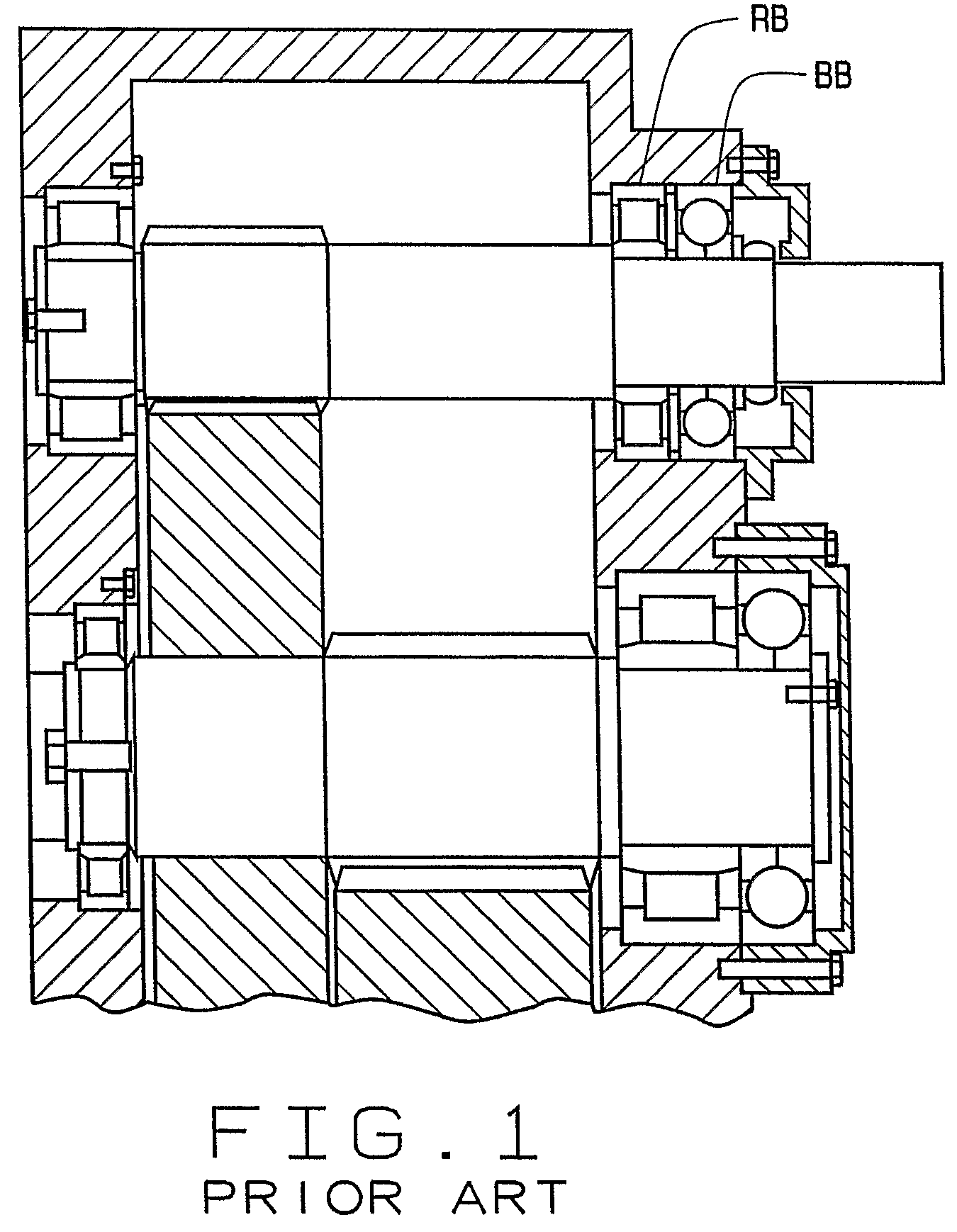
In particular, the combination bearing assembly of FIG. 1 and the spherical roller bearing styles mentioned above experience performance problems manifested with smearing of raceway surfaces, micropitting and retainer failure.
The objection to this solution is that close control of adjustment is critical and not easy to obtain reliably.
Another solution is to fix a 2-row spherical roller bearing that eliminates the need for on-sight adjustment of clearances, but this style bearing experiences damage to raceways and retainers because it is not a particularly good bearing style for combined radial and thrust loading when the proportion of thrust load is high and / or reversing.
The dynamics of torque reversing from positive (during power generation) and negative (during motoring) produces excessive roller sliding / skidding and these forces strain the retainers.

Method used


Image

  • Locating bearing assembly for wind turbine gearbox shaft
  • Locating bearing assembly for wind turbine gearbox shaft
  • Locating bearing assembly for wind turbine gearbox shaft

Examples


Embodiment Construction

[0012]The following detailed description illustrates the invention by way of example and not by way of limitation. This description will clearly enable one skilled in the art to make and use the invention, and describes several embodiments, adaptations, variations, alternatives and uses of the invention, including what we presently believe is the best mode of carrying out the invention. Additionally, it is to be understood that the invention is not limited in its application to the details of construction and the arrangements of components set forth in the following description or illustrated in the drawings. The invention is capable of other embodiments and of being practiced or being carried out in various ways. Also, it is to be understood that the phraseology and terminology used herein is for the purpose of description and should not be regarded as limiting.

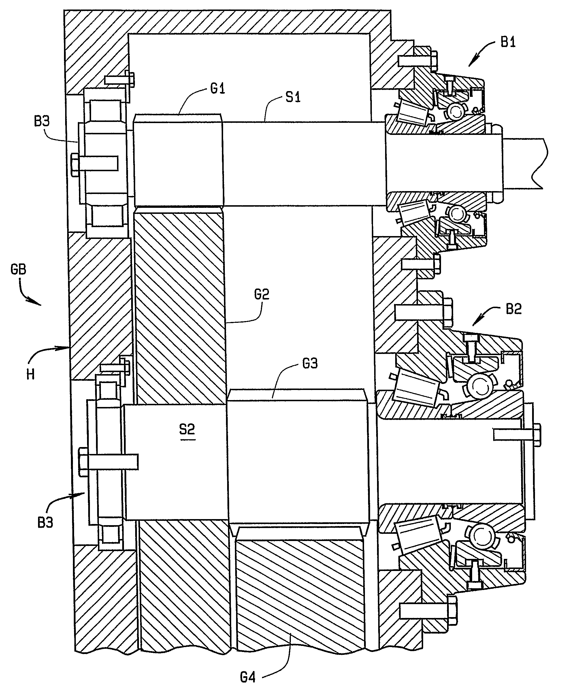
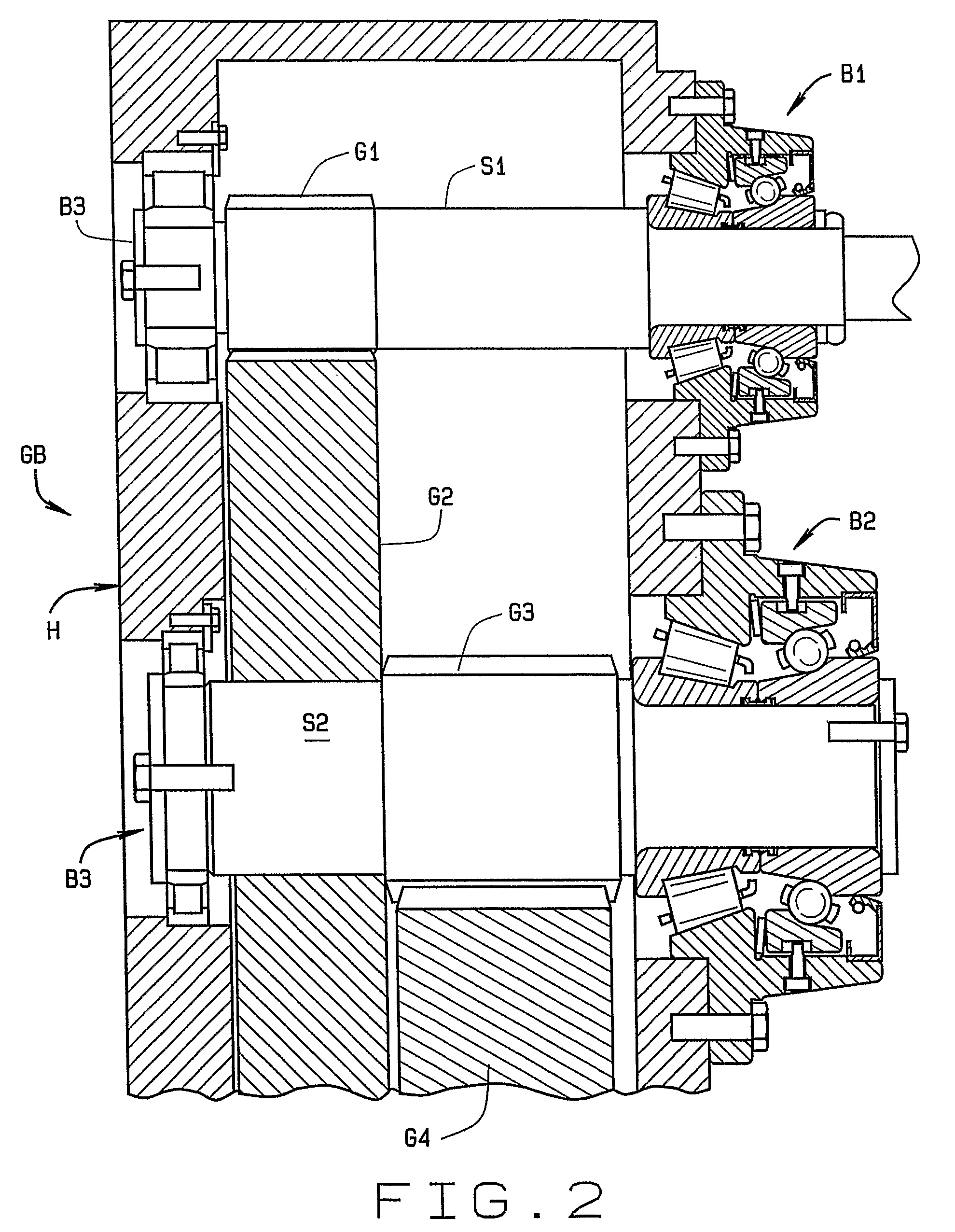
[0013]A gearbox GB for a wind turbine is shown generally in FIG. 2. The gearbox GB includes a housing H which supports mul...


PUM


Abstract

A locating bearing assembly (10) is provided that optimizes load distribution between bearing rows and for all rolling elements within the rows in either positive or negative torque conditions, by combining a single row tapered roller bearing with an angular contact ball bearing. The outer race (60) for the ball bearing is preloaded by a spring element (72) to prevent the balls (26) from floating freely between the ball bearing's inner and outer raceways (16, 64). This will insure that the balls (26) are always sufficiently loaded to roll along a single axis which is off set from the radial direction. The use of the single row tapered bearing and the preloaded angular contact ball bearing provides for a locating bearing assembly (“LBA”) in which the ball bearing supports only reversing axial loads. All radial loads are borne by the tapered roller bearing and transmitted to the bearing assembly housing (30).

Description

CROSS-REFERENCE TO RELATED APPLICATIONS[0001]This application is the national phase application under 35 U.S.C. §371 of International Application No. PCT / US2005 / 015894 and which claims priority to U.S. Provisional App. No. 60 / 568,984 filed May 7, 2004 and which is incorporated herein by reference.TECHNICAL FIELD[0002]This invention relates to wind turbine generators, and, in particular, to a new and improved bearing assembly for a wind turbine gearbox.BACKGROUND ART[0003]Wind turbine generators are frequently equipped with gearboxes that increase shaft speed of the rotor blades to an output shaft speed to the generator by step up ratios as high as 100 to 1. For example, if the rotor blades are rotating at 20 RPM, the output shaft of the gearbox might be 2000 RPM. The speed and angular acceleration produced create a varying and difficult set of dynamic conditions for the output shaft. Output shafts (as well as the shafts they mesh with) are generally parallel gear shafts equipped wit...

Claims


Application Information

Patent Timeline
Patent Type & Authority Patents(United States)
IPC IPC(8): F16C19/49F03D11/00F03D11/02F16C19/54F16C35/077F16H57/02
CPCF03D11/0008F03D11/02F16C19/497F16C25/083F16C33/60F16C19/543F05B2240/50F05B2260/4031F16C2360/31F16H57/021Y02E10/722F03D80/70F03D15/00F16C2361/61F03D15/10Y02E10/72F16H37/041
Inventor FOX, GERALD P.RHODES, JOHN H.
Owner THE TIMKEN CO
Learn More