Core sampling device intended to assemble tissue arrays

a sampling device and tissue technology, applied in the field of tissue array production techniques, can solve the problems of slow and cumbersome use of such a device, and achieve the effect of simple design and easy implementation by users

Active Publication Date: 2009-08-11
MITOGEN
View PDF5 Cites 4 Cited by
  • Summary
  • Abstract
  • Description
  • Claims
  • Application Information

AI Technical Summary

Benefits of technology

[0008]The aim of the present invention is to supply a core sampling device that is of simple design, easy to implement by the user and which overcomes the above drawbacks.
[0016]According to yet another characteristic of the invention, the punches have a sharp edge intended to facilitate their penetration into the paraffin or the frozen block as well as to facilitate the extraction of the cores.
[0018]A first advantage of the device according to the invention lies in the fact that it enables the pathologists to study a large number of patients simultaneously with a restricted budget and within a limited lapse of time. This thus enables a great acceleration in the progress of research knowledge into new prognostic and diagnostic methodologies, and thus into new treatments.

Problems solved by technology

Moreover, the position of the donor block support platform must be modified at every operation thereby making the use of such a device both slow and cumbersome.

Method used


Image

  • Core sampling device intended to assemble tissue arrays
  • Core sampling device intended to assemble tissue arrays
  • Core sampling device intended to assemble tissue arrays

Examples


Embodiment Construction

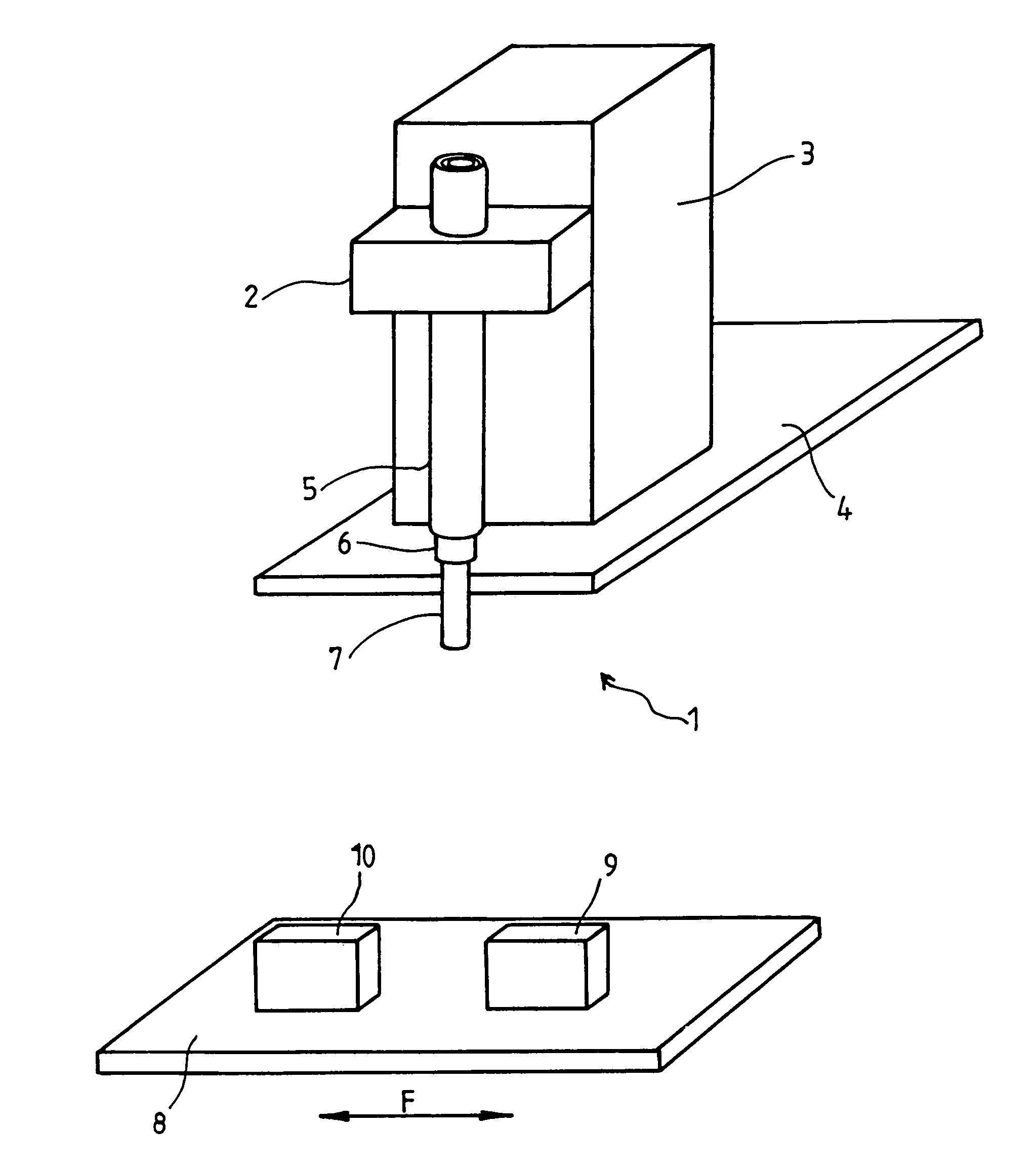
[0023]FIG. 1 shows a core extraction device 1 mounted on a support 2 itself integral with a frame 3 fixed onto a support plate 4 intended to support all the elements required for the operation of the device, such as a hydraulic or electrical power unit required to control the different elements, as will be explained hereafter. It classically incorporates a core extraction punch 6 and a core sampling punch 5.

[0024]According to the invention, these two punches 5 and 6 are arranged aligned along the same longitudinal axis and defining an inner punch and an outer punch. For the rest of the description, the terms external punch 5 and internal punch 6 will be used. The support 2 receives the external punch 5, the internal punch 6 and an ejector 7. These three parts are mounted aligned along the same axis and able to slide with respect to one another. Punches 5 and 6 are in the form of two tubes, internal punch 6 being inserted in external punch 5. These two punches slide forwards and back...


PUM

PropertyMeasurementUnit
external diameteraaaaaaaaaa
internal diameteraaaaaaaaaa
rotationaaaaaaaaaa

Abstract

A core sampling device includes a core sampling punch, a core excision punch that makes a recess in a receiver body, and an ejector that expels a sample core into the receiver body. The core excision punch is mounted inside the core sampling punch and is substantially coaxial with the core sampling punch. Both punches are able to move in translation and / or rotation with respect to one another, and the ejector is arranged so as to expel cores from each punch.

Description

BACKGROUND OF THE INVENTION[0001]1. Field of the Invention[0002]The technical scope of the present invention is that of techniques to produce tissue arrays.[0003]2. Description of the Related Art[0004]The tissue array is a technique to mount sections of biological tissues onto microscope slides for their future visual or electronic analysis. The tissue array technique enables a large number of tissue sections to be mounted onto the same slide contrary to the technique traditionally practiced in pathology laboratories where only one to three sections may be mounted together.[0005]The tissue array techniques consist in taking one or several cores from several dozen, or even several hundred, different blocks containing tissue samples either embedded in paraffin or frozen. All the cores are then assembled in a paraffin block or in a frozen inclusion milieu in which recesses have been made.[0006]The tissue array technique is well known and requires no further description here.[0007]Refer...

Claims


Application Information

Patent Timeline
Patent Type & Authority Patents(United States)
IPC IPC(8): B01L3/00A01N1/00A01N1/02G01N21/00G01N15/06C12M3/00C12M1/26A61B10/00
CPCC12M33/00C12M3/00
Inventor CHAUMAT, PIERRE
Owner MITOGEN
Why Eureka
Try Eureka