
Light emitting diode package

a technology of light-emitting diodes and led packages, which is applied in the direction of semiconductor devices, semiconductor/solid-state device details, electrical apparatuses, etc., can solve the problems of affecting the optical performance of led packages and the inability to dispose of the nozzle required in the injection molding process

Active Publication Date: 2009-08-11
TCL CHINA STAR OPTOELECTRONICS TECH CO LTD
View PDF3 Cites 11 Cited by
  • Summary
  • Abstract
  • Description
  • Claims
  • Application Information

AI Technical Summary

Benefits of technology

This method significantly reduces air remaining in the encapsulants, improves optical performance, and simplifies the manufacturing process by avoiding the need for vacuum equipment, thereby reducing costs and preventing air flush-back phenomena.

Problems solved by technology

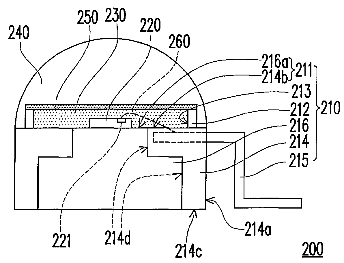
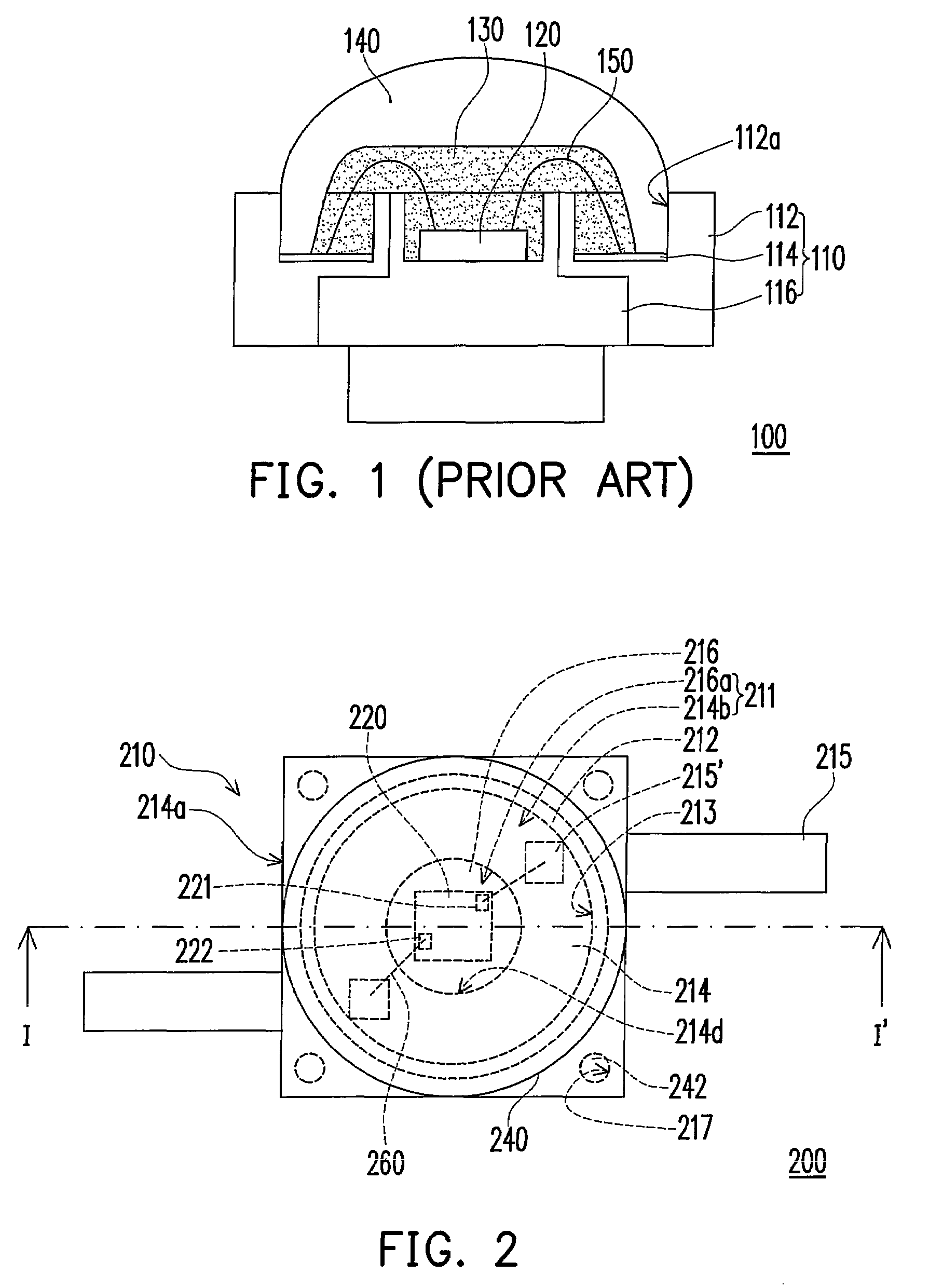
However, said vacuum process does not result in a perfect vacuum between the transparent cap 140 and the leadframe 110, and thus some air still remains in the transparent encapsulant 130, which adversely affects the optical performance of the LED package 100.
Nevertheless, due to the small size of the LED package, a nozzle required in the injection molding process is not apt to be disposed.

Method used


Image

  • Light emitting diode package
  • Light emitting diode package
  • Light emitting diode package

Examples


Embodiment Construction

[0023]In the following detailed description of the preferred embodiments, reference is made to the accompanying drawings which form a part hereof, and in which is shown by way of illustration specific embodiments in which the invention may be practiced. In this regard, directional terminology, such as “top,”“bottom,”“front,”“back,” etc., is used with reference to the orientation of the Figure(s) being described. The components of the present invention can be positioned in a number of different orientations. As such, the directional terminology is used for purposes of illustration and is in no way limiting. On the other hand, the drawings are only schematic and the sizes of components may be exaggerated for clarity. It is to be understood that other embodiments may be utilized and structural changes may be made without departing from the scope of the present invention. Also, it is to be understood that the phraseology and terminology used herein is for the purpose of description and ...


PUM

PropertyMeasurementUnit
transparentaaaaaaaaaa
shock resistanceaaaaaaaaaa
electricallyaaaaaaaaaa

Abstract

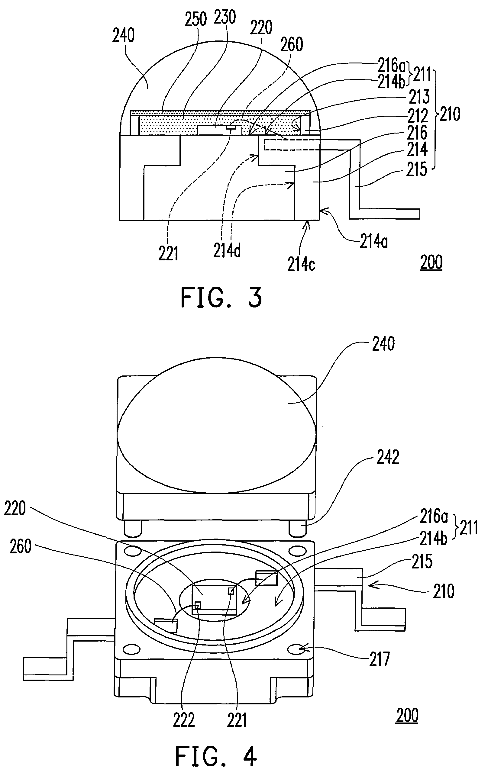
A light emitting diode (LED) package including a carrier, an LED chip, a first transparent encapsulant, a transparent cap, and a second transparent encapsulant is provided. The carrier has a carrying surface and a ring frame disposed on the carrying surface, and the ring frame forms an encapsulant-containing space on the carrying surface. The LED chip is disposed on the carrying surface and in the encapsulant-containing space. The LED chip is electrically connected to the carrier. The first transparent encapsulant fills the encapsulant-containing space to encapsulate the LED chip. The transparent cap is disposed on the carrier to cover the first transparent encapsulant and the ring frame. The second transparent encapsulant fills an interval between the first transparent encapsulant and the transparent cap.

Description

CROSS-REFERENCE TO RELATED APPLICATION[0001]This application claims the priority benefit of Taiwan application serial no. 96103497, filed Jan. 31, 2007. All disclosure of the Taiwan application is incorporated herein by reference.BACKGROUND OF THE INVENTION[0002]1. Field of the Invention[0003]The present invention relates to a chip package, and more particularly to a light emitting diode (LED) package.[0004]2. Description of Related Art[0005]Due to numerous advantages of long life span, miniature size, high vibration and shock resistance, low heat generating, low power consumption and so on, light emitting diodes (LEDs) have been widely applied to indicating lights or light sources employed in a variety of household electric appliances and instruments. With recent development towards multicolor and high illumination, the applications of the LEDs are extended to large-sized outdoor billboards, traffic lights, etc. In the future, the LEDs may become the power-saving and environment-fr...

Claims


Application Information

Patent Timeline
Patent Type & Authority Patents(United States)
IPC IPC(8): H01L33/00H01L33/48H01L33/52H01L33/58
CPCH01L33/52H01L33/486H01L33/58H01L2224/48091H01L2924/00014
Inventor CHANG, HSI-SHENG
Owner TCL CHINA STAR OPTOELECTRONICS TECH CO LTD
Learn More