One time programmable element system in an integrated circuit

a one-time programmable element and integrated circuit technology, applied in the field of integrated circuits, can solve the problem that the reduction rate of the size of the fuse is not nearly the same as the reduction ra

Active Publication Date: 2009-08-11
NXP USA INC
View PDF14 Cites 82 Cited by
  • Summary
  • Abstract
  • Description
  • Claims
  • Application Information

AI Technical Summary

Problems solved by technology

One challenge with implementing OTP elements such as a fuse in an integrated circuit is that fuse size reduction has not advanced at nearly the same rate as the reduction in size of transistor features.

Method used


Image

  • One time programmable element system in an integrated circuit
  • One time programmable element system in an integrated circuit
  • One time programmable element system in an integrated circuit

Examples


Embodiment Construction

[0018]The following sets forth a detailed description of a mode for carrying out the invention. The description is intended to be illustrative of the invention and should not be taken to be limiting.

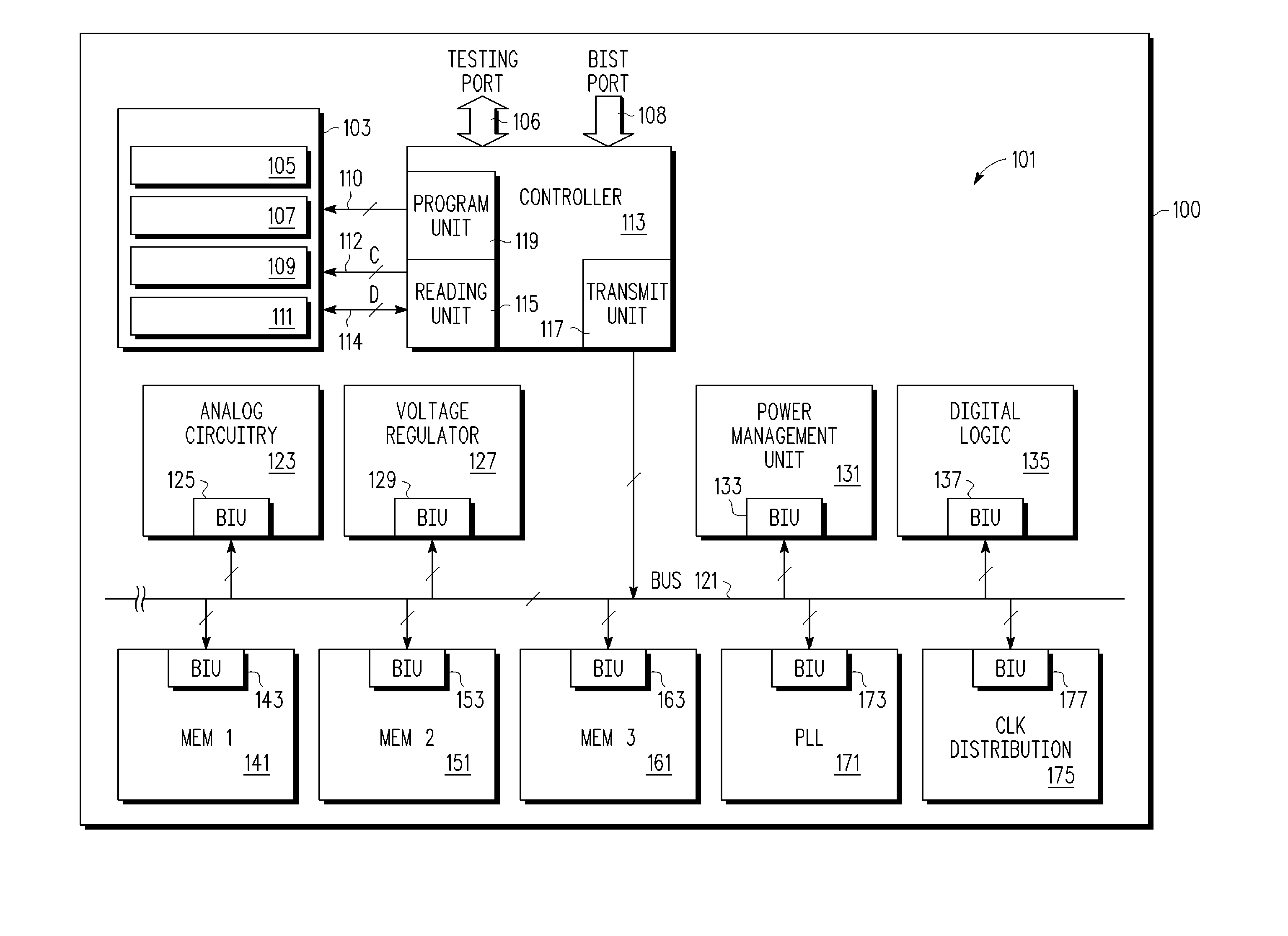
[0019]FIG. 1 is a block diagram of a fuse system of an integrated circuit 100. Fuse system 101 allows for the ability to utilize a programmable fuse among any one of a number of devices, thereby providing flexibility of the fuse system in an integrated circuit. Integrated circuit 100 can also include other fuse systems similar to fuse system 101. Each of these systems can be associated with either memory array circuits or non memory array circuits, or a combination of memory array and non memory array circuits.

[0020]System 101 includes a fuse array circuit 103 that includes a plurality of fuse banks with fuse banks 105, 107, 109, and 111 shown in FIG. 1. System 101 includes a fuse controller 113. Fuse controller 113 includes program unit 119 for programming the fuses of fuse array circui...


PUM


Abstract

A system with a repairable memory array having redundant memory cells to replace one or more defective memory cells that are detected after fabrication. The system also includes non memory array circuits having circuitry that may adjust one or more operating parameters such as operating current, operating voltage, resistance, capacitance, timing characteristics and an operating mode. A set of one time programmable elements can be used to selectively store information for modifying operating parameters and replacing the defective memory cells with redundant memory cells.

Description

BACKGROUND OF THE INVENTION[0001]1. Field of the Invention[0002]This invention relates in general to integrated circuits and more specifically to integrated circuits with one time programmable elements.[0003]2. Description of the Related Art[0004]One time programmable (OTP) elements such as fuses and PROM cells are utilized in integrated circuits for adjusting the circuitry after fabrication of an integrated circuit. For example, a programmable fuse may be used to adjust circuitry of an integrated circuit for specific conditions or correct for manufacturing defects.[0005]One specific use of OTP elements is for providing repair information that controls the usage of redundant cells in replacing defective cells of a memory array. Another use is for tuning analog circuitry by trimming a capacitive or resistive value of an analog circuit or enabling and disabling portions of the system. A recent trend is that the same product is likely to be manufactured in different fabrication facilit...

Claims


Application Information

Patent Timeline
Patent Type & Authority Patents(United States)
IPC IPC(8): G11C29/00
CPCG11C17/18G11C17/16G11C5/147G11C29/70
Inventor KENKARE, PRASHANT U.ZIMIN, MICHAEL
Owner NXP USA INC
Why Eureka
Try Eureka