Oral implant template

a template and implant technology, applied in the field of oral implant drilling template, can solve the problems of undesirable clinic use of cnc machine, inability to support adjacent teeth with drilling template, improper alignment of drilling guides, etc., and achieve the effect of easy manipulation of said impression

Inactive Publication Date: 2009-08-11
I DENT IMAGING
View PDF13 Cites 92 Cited by
  • Summary
  • Abstract
  • Description
  • Claims
  • Application Information

AI Technical Summary

Benefits of technology

[0025]Optionally, said negative jaw impression is adjusted during formation to allow easy manipulation of said impression on said recipient jaw. Optionally one or more tooth implant models are set in said negative jaw impression prior to producing said images.
[0031]In an exemplary embodiment, said 3D digital image is enhanced to allow easy manipulation within said recipient jaw. Optionally, said recipient jaw model is used to produce a negative template of said model.

Problems solved by technology

Use of a CNC machine, though, is undesirable in a clinic setting.
Prior art image correction software, unfortunately, relies on default settings to reconstruct the jaw image hidden by artifact distortion, a process wherein the software estimates the distorted jaw boundaries.
A drilling template that is made according to this estimated jaw model may not be supported by adjacent teeth and / or may have improperly aligned drilling guides.
Another problem in constructing a pleasing implanted tooth using the boundary method, occurs in properly mounting the finished drilling template on the recipient jaw area.
When the teeth adjacent to the planned implants have complex concavity and / or convexity, the resultant drilling template often is difficult to mount or remove from the jaw.
In the presence of such curvature complexity, imaging software will often rely on default settings to smooth out such curvatures, again yielding a drilling template with improper drilling guides and resultant aesthetically displeasing implanted teeth.
This method of drilling a negative impression is cumbersome and, worse, imprecise.
This results in image aberrations that his method cannot correct, yielding a drilling template from which misaligned implant bores are drilled or an unusable drilling template.
Swaelens et al., WO 95 / 28688 provides an imaging method for determining muscle and tendon position that may be helpful in determining tooth implant bore location, but fails to teach how to correct surface boundaries distorted by metal inserts or correct for complicated tooth curvatures.
As a result, the resultant drilling template may provide inaccurate bore placement and aesthetically displeasing results.

Method used


Image

  • Oral implant template
  • Oral implant template
  • Oral implant template

Examples


Embodiment Construction

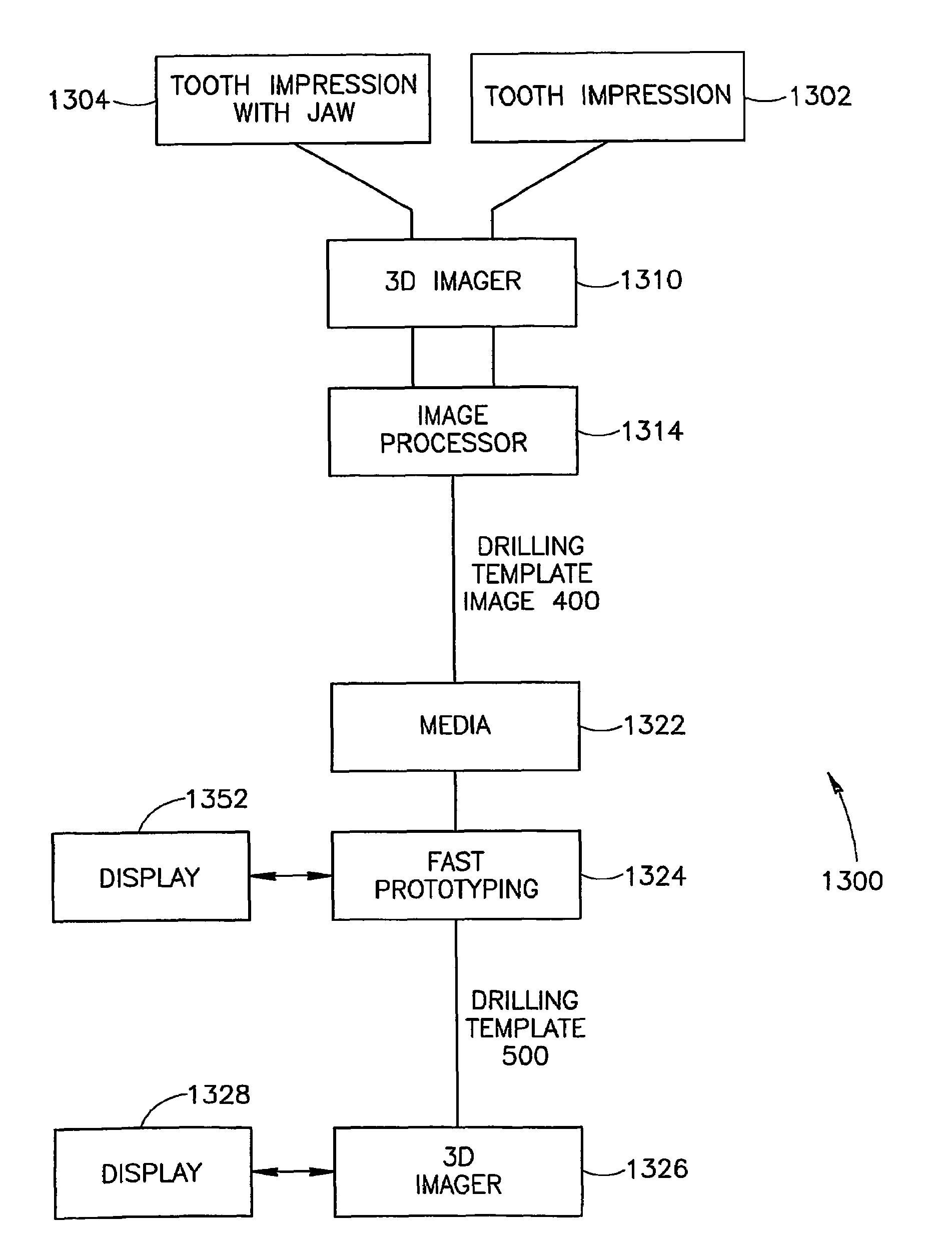
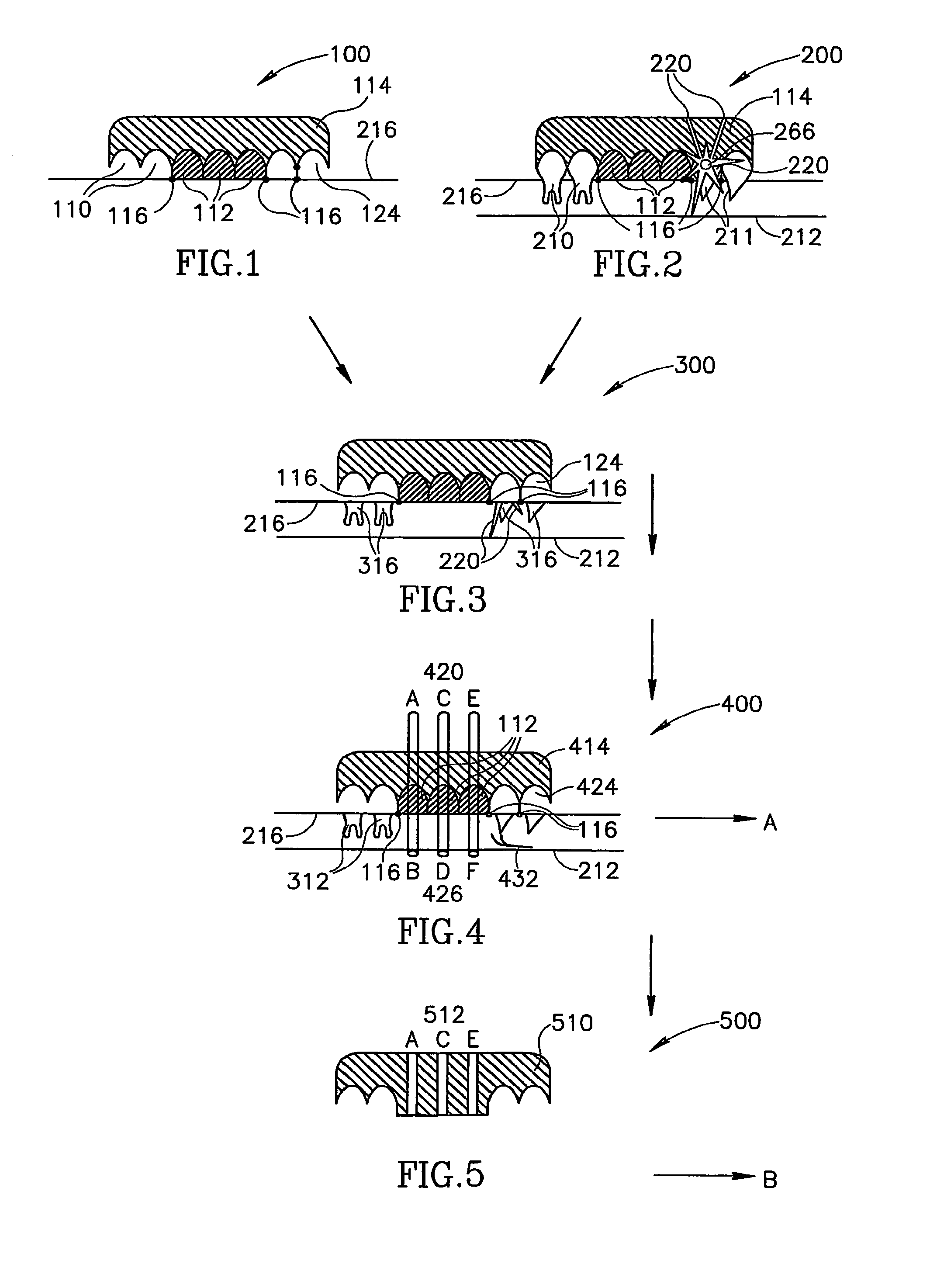
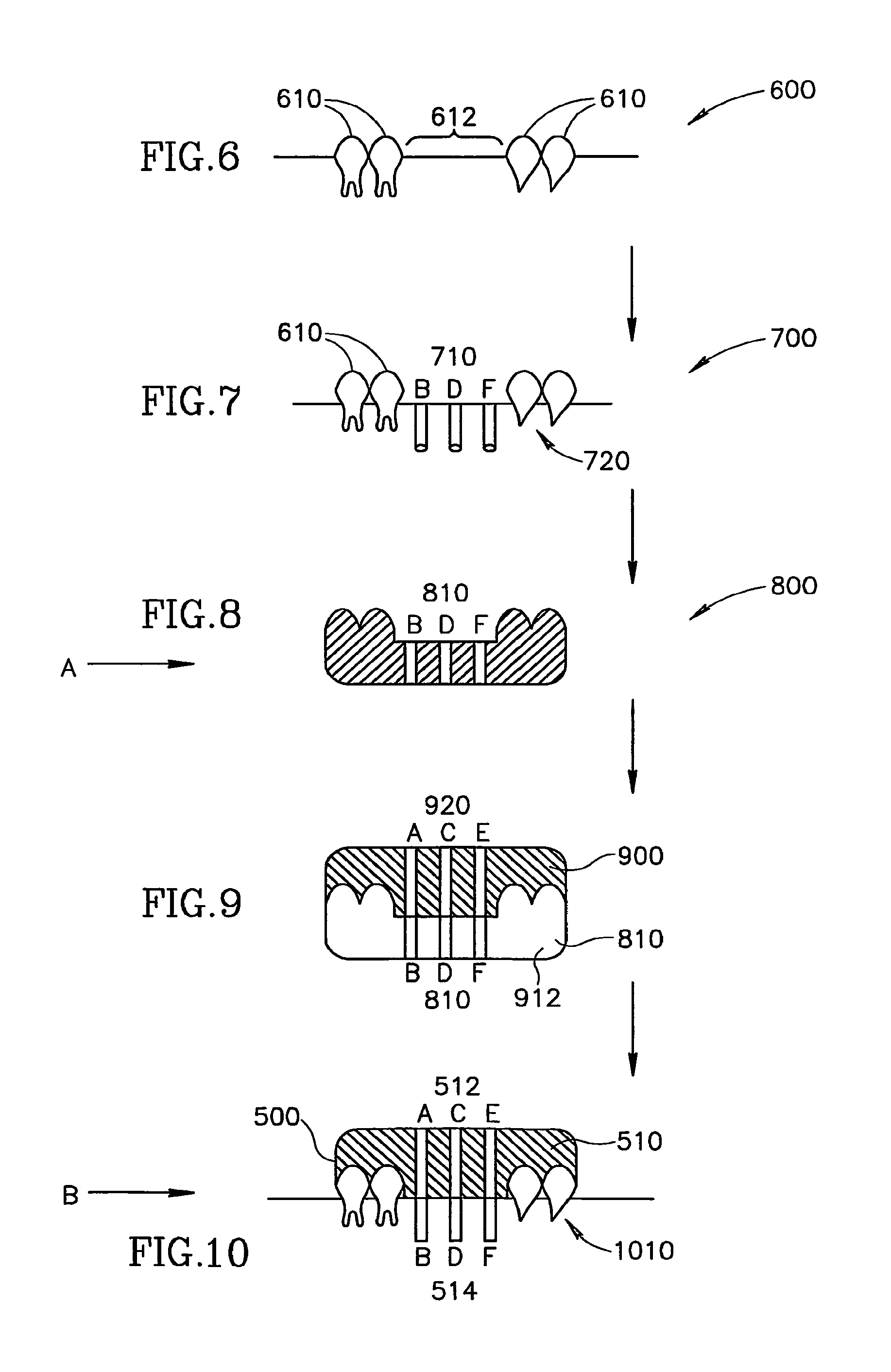
[0056]An aspect of the present invention relates to producing an artifact-corrected image of a recipient jaw and its negative impression as a basis for creating a drilling template with properly aligned drill guides for drilling implant-receiving bores in a recipient jaw. To understand this process, reference will be made to a flow chart 1100 in FIG. 11, interspersed with references to FIGS. 1 through 4.

[0057]In flow chart 1100 of FIG. 11, at 1110, a negative impression is made of the recipient jaw. Optionally, the negative impression at 1110 is prepared using a three-step mechanical impression method known in the art. First, a negative replica is taken directly from the patient teeth by conventional methods, for example using elastic viscose. The negative replica is filled with a hard material, for example gypsum (plaster) to form a replica of the implant area. A third (negative) impression is taken of the replica of the implant area. While a negative impression is made in three st...


PUM


Abstract

A method for producing an artifact-corrected image of a negative jaw impression in a recipient jaw comprising, forming a negative impression of said recipient jaw, producing a first digital image of said negative jaw impression, producing a second digital image, including said artifacts of said negative jaw impression in said recipient jaw and using said first digital image to produce an artifact-corrected computer representation of said negative impression in said recipient jaw.

Description

RELATED APPLICATION[0001]This application claims benefit under 119(e) of U.S. provisional patent application 60 / 348,382, filed Jan. 16, 2002, the disclosure of which is incorporated herein by reference.FIELD OF THE INVENTION[0002]The present invention relates to creating an oral implant drilling template.BACKGROUND OF TIE INVENTION[0003]A drilling template is a negative blank of a recipient jaw with at least one drilling guide for positioning one or more tooth implant bores in the recipient jaw. An aesthetically pleasing implanted tooth is dependent upon proper bore placement and depth in relation to other teeth, placement in appropriate jaw bone stock and duplication of the angle of adjacent teeth in the recipient jaw, all of which must be incorporated into the drilling template. For the purposes of this application, the words “recipient jaw” refers to the teeth, gums, landmarks, supportive and ancillary structures within the area that is designated to receive an implant.[0004]In o...

Claims


Application Information

Patent Timeline
Patent Type & Authority Patents(United States)
IPC IPC(8): G06K9/00A61C3/00G06K9/40A61C19/04A61B5/055A61B6/03A61B6/14A61C1/08A61C8/00A61C9/00A61C13/00G06T17/40
CPCA61C1/084A61C9/00A61C13/0004A61C9/004A61B6/5258
Inventor FELDMAN, ANDREI
Owner I DENT IMAGING
Why Eureka
Try Eureka