Process and device for conveying odd-shaped containers

a technology of odd-shaped containers and conveying devices, which is applied in the direction of caps, furniture, charge manipulation, etc., can solve the problems of poor line conveyance, container shape that cannot be easily conveyed, and long slender containers that are typically long, etc., and achieves stable surface, aesthetic qualities of the formed container shape, and added stability

Active Publication Date: 2009-08-18
CO2 PAC
View PDF176 Cites 54 Cited by
  • Summary
  • Abstract
  • Description
  • Claims
  • Application Information

AI Technical Summary

Benefits of technology

[0011]In summary, the instant invention employs a transfer stabilizing support that temporarily surrounds a bottom end of a blow-molded or other formed container to provide a stable surface and add temporary weight so that the container can be easily conveyed in the table-top manner through the filling, capping and cooling operations, if necessary. The process for conveying top-heavy and odd-shaped containers, according to the invention, temporarily secures a transfer stabilizing support to the bottom end of a formed container so that the container can freely move along a production line in the table-top manner, and after the container has gone through the production line, the transfer stabilizing support is removed so that the aesthetic qualities of the formed container shape are revealed. As stated above, the transfer stabilizing support, according to the invention, adds temporary weight to the bottom of a lightweight container and / or top-heavy containers to provide both added stability and enhanced handling characteristics.

Problems solved by technology

However, the shape of some of the containers do not lend themselves to be conveyed along a production line in the table-top fashion.
The wider upper portion and the narrower bottom end, while having a relatively smooth surface, produce a container that cannot be easily conveyed when the container is empty, because the upper end produces a top-heavy empty container that may topple over on its side when the container is pushed via air or other means.
Similarly, long slender containers typically have poor line conveyance due to a high center of gravity.
Thus, such odd-shaped containers either cannot be conveyed in the table-top fashion, or their conveyance in a table-top fashion results in numerous toppled containers and requires costly, constant supervision to facilitate the movement of the containers through the production line.
Consequently, a complex system of conveyors was thought necessary in order to convey the odd-shaped container through the filling, capping, batching and cooling operations.
Such a complex system of conveyors for a production line is a costly investment since it may only be useful for a single odd-shaped container.
However, this method adds to the instability of the formed lightweight container, as it is conveyed in a conventional table-top system, as the center of gravity moves upwards as gram weight is removed from the bottom and sidewalls of the container resulting in a container that is easier to tip over.
This trend for lightweight containers and the trend to move the vacuum compression panels to the lower third of the container presents a challenge in conveying the new containers in a cost-efficient manner.
While neck conveying guide rails may be suitable for conveying some containers along a portion of a production line, the neck rail conveyor is not suitable for entry into a cooling tunnel and exiting therefrom, as a cost-effective, cooling operation is typically achieved by cooling a number of the containers at one time.
Accordingly, reliance on a rail neck conveying system would involve such inefficiencies as changing the entire rail neck conveying system to enable the conveying of a different type of container, such as a container with a different sized neck.
This would result in an unacceptable level of downtime and would limit the design of containers used by this specialized rail device to a small number of containers.

Method used


Image

  • Process and device for conveying odd-shaped containers
  • Process and device for conveying odd-shaped containers
  • Process and device for conveying odd-shaped containers

Examples


Embodiment Construction

[0029]Embodiments of the invention are discussed in detail below. In describing embodiments, specific terminology is employed for the sake of clarity. However, the invention is not intended to be limited to the specific terminology so selected. While specific exemplary embodiments are discussed, it should be understood that this is done for illustration purposes only. A person skilled in the relevant art will recognize that other components and configurations can be used without parting from the spirit and scope of the invention. All references cited herein are incorporated by reference as if each had been individually incorporated.

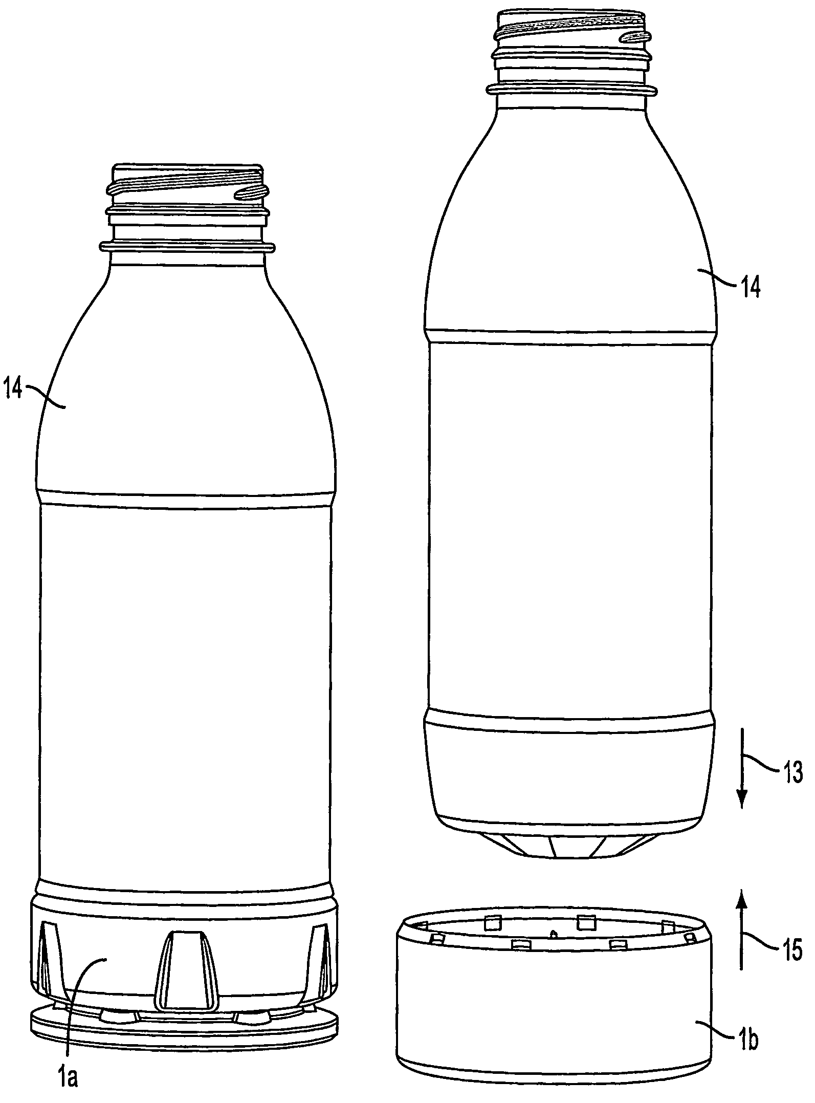
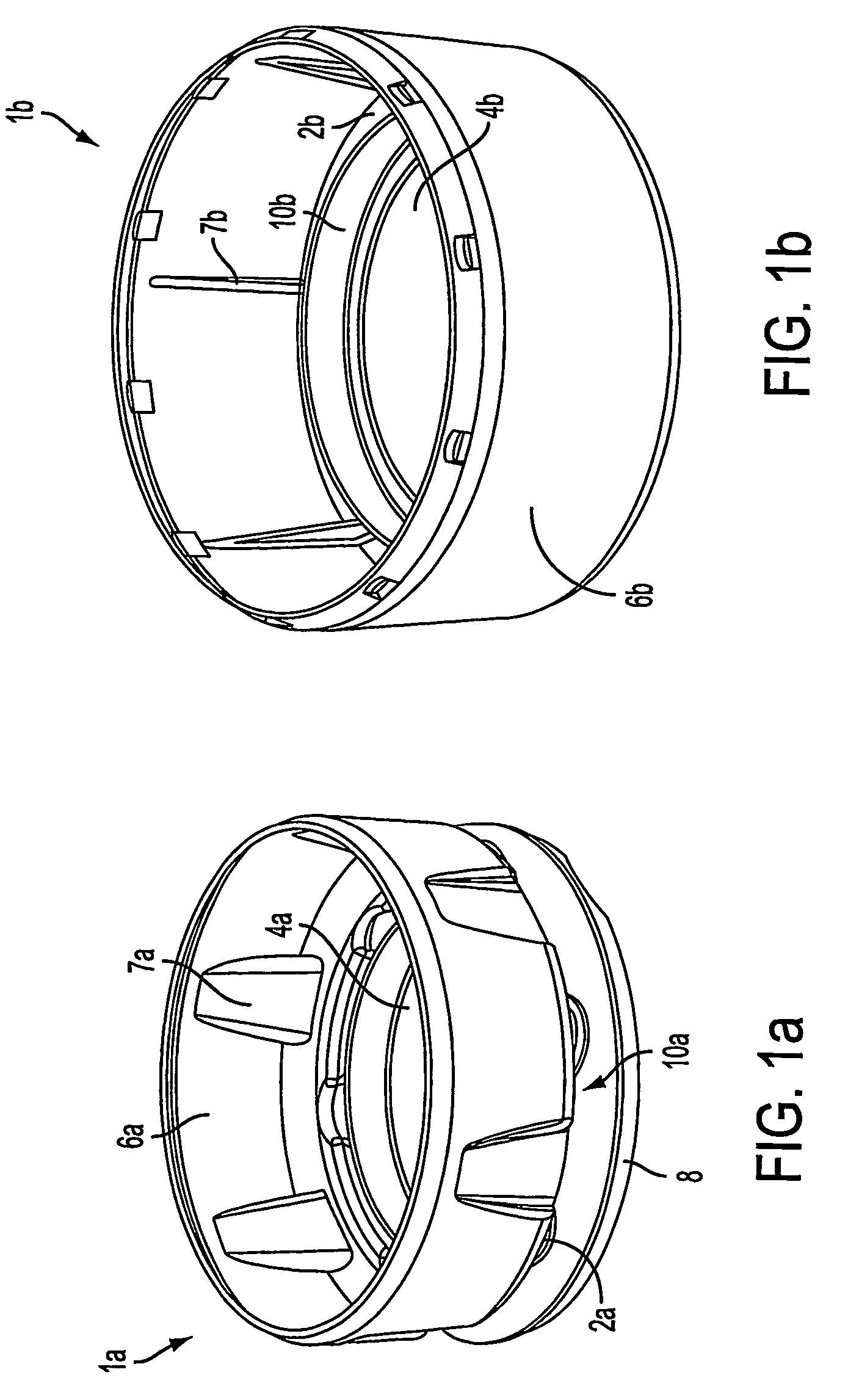
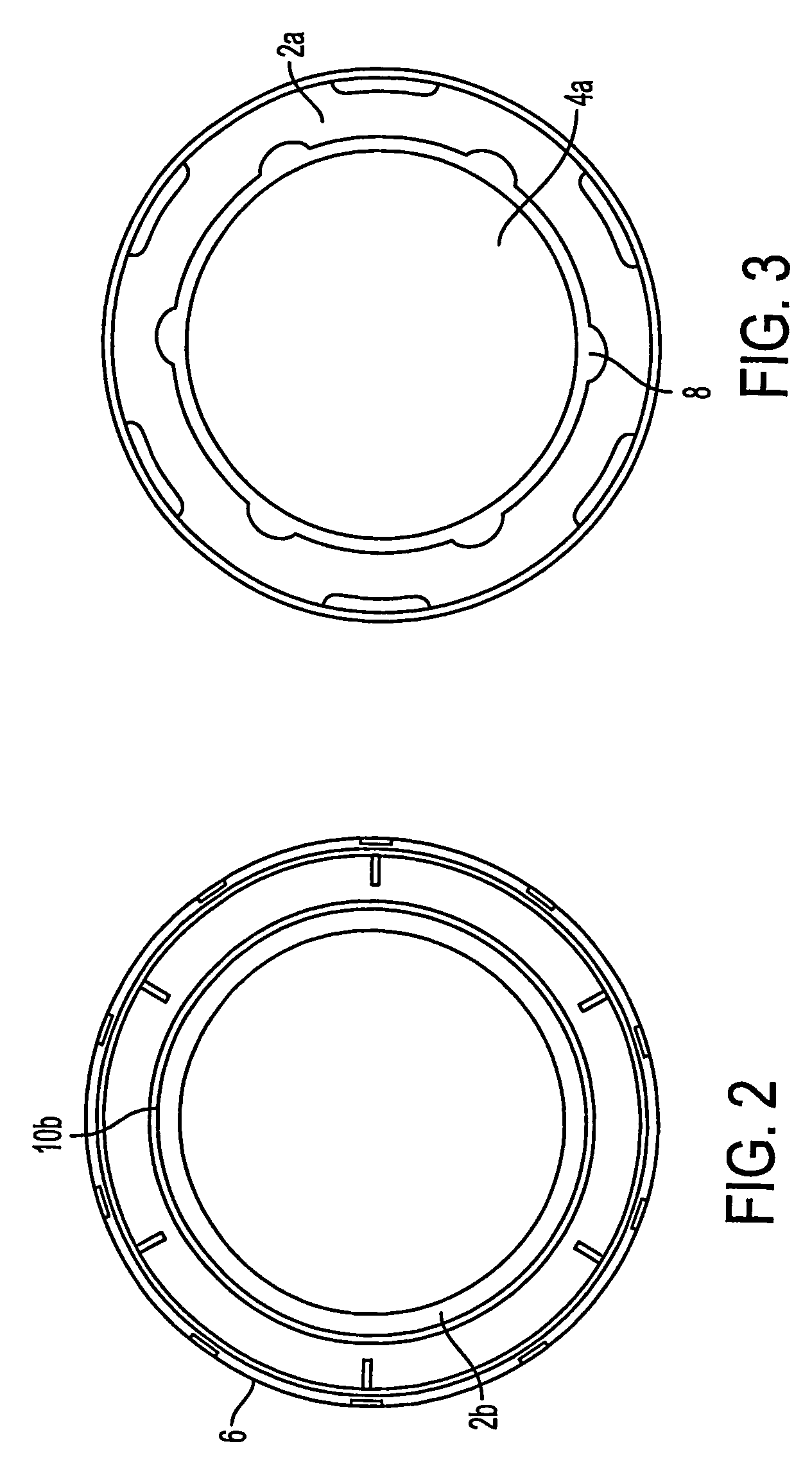
[0030]Looking at FIGS. 1a and 1b, two embodiments of the inventive, transfer stabilization support 1a and 1b are shown, which when secured to a container provide stability and enhanced handling characteristics to a conveyed container. Each support 1a, 1b has a bottom surface 2a, 2b with an opening 4a, 4b and a wall 6a, 6b extending perpendicularly from an...


PUM

PropertyMeasurementUnit
heightaaaaaaaaaa
frictionaaaaaaaaaa
plasticaaaaaaaaaa

Abstract

A process for efficiently conveying containers along a table-top conveying system includes the steps of temporarily securing a transfer stabilizing support (1a, 1b) to a bottom end of a formed container (14) so that the container can freely move along a production line using the table-top conveying system where the transfer stabilizing support has a bottom surface (2a, 2b) with an opening (4a, 4b), a sidewall (6a, 6b) extending substantially perpendicular to the bottom surface, and a ridge area (10b) surrounding the opening and inside the sidewall of the support; and after the container has gone through operations of the production line, the transfer stabilizing support is removed so that aesthetic qualities of the formed container shape are revealed.

Description

BACKGROUND OF THE INVENTION[0001]1. Field of the Invention[0002]The present invention relates generally to the conveyance of unstable, empty containers in a production line, and more particularly to a transfer stabilization support that temporarily attaches to a top-heavy or odd-shaped container with a non-round bottom surface end so that the top-heavy or odd-shaped container can be easily conveyed throughout the production line.[0003]2. Related Art[0004]Typically, containers are formed with a stable base surface so that the containers can easily be conveyed in a table-top fashion along a production line. Generally, containers are moved freely through a production line by standing the container on its base surface and pushing the container via air along the production line. The production line may start when the container exits the container forming operation and continue to filling and capping operations and then to a cooling operation, if necessary. However, the shape of some of t...

Claims


Application Information

Patent Timeline
Patent Type & Authority Patents(United States)
IPC IPC(8): B65B63/08B65B7/28B67C3/24B65G17/46B65G37/02
CPCB65D1/0261B65G17/46B65G2201/0261B65G2201/0244
Inventor SHEETS, PHILIPKELLEY, PAULDENNER, JOHN
Owner CO2 PAC
Why Eureka
Try Eureka