Hybrid microturbine for generating electricity

a microturbine and hybrid technology, applied in the direction of machines/engines, stators, liquid fuel engines, etc., can solve the problems of high total system cost, low efficiency of parts, and inability to optimize parts power fuel economy, etc., to achieve low emission, increase cycle pressure ratio, and low weight

Active Publication Date: 2009-08-18
TEETAB JOSEPH MICHAEL +1
View PDF19 Cites 40 Cited by
  • Summary
  • Abstract
  • Description
  • Claims
  • Application Information

AI Technical Summary

Benefits of technology

[0015]Another object is to provide a electric power generating system with two rotor spools one as a turbo charger and the other spool incorporates an alternator to create electrical energy thru the use of a gas turbine engine. This will yield a compact, low weight, low emission, reduced cost, multi-fuel use, vibration free, high durability and black start capable hybrid microturbine. Also will remove the need for a recuperator / regenerator, decreasing the initial cost and increasing durability.
[0016]Another object is to provide an electric power generating system having two rotor spools, one acting as a turbo-charger and the other spool with an integrated alternator to generate electricity has modular rotor / spools either as a (2) piece system (for housing installation) in the #2 spool or as a (1) piece type in the #1 spool modular system. Oil squeeze film dampers are incorporated in the outer most modular areas and interact with the respective static engine housings. This arrangement allows not only good rotor damping but yields the capability of optimum final spool balance without disassembly and subsequent reassembly in the engine housings. With this described rotor system / overhung type design subassembly, a greater range of engine rotor speed (rpm) can be attained yielding improved component compressor and turbine efficiencies through minimized airflow and blade to case clearance along with lower speeds for off-design power requirements thus allowing improved fuel efficiency.
[0017]Another object is to provide an electric power generating system, having two rotor spools, one acting as a turbo charger and the #2 rotor spool having an integrated alternator to generate electricity, have rotor spool subassembly shaft seals and related bearing mounts have a common dampened housing yielding less shaft to seal excursions—minimizing related compressor air seal flow leakage.
[0018]Another object of this hybrid microturbine invention is to provide a electric power generating system, having two rotor spools, one acting as a turbo charger and the 2nd rotor spool having an integrated alternator to generate electricity is to reduce the turbine power necessary to drive the compressor allowing more available to drive the related alternator, thus improve fuel economy. A preferred embodiment could incorporate a moveable plate or vanes within a divergent supply duct communicating with the #2 compressor inlet allowing in one configuration reduced air duct supply velocity for direct air flow radially toward the rotor axis or impart an air preswirl (with rotation) to optimize the related inlet blade incidence angle thus reducing the require power to drive the compressor.
[0019]Another object of this invention is to provide an electric power generating system, having two rotor spools, one acting as a turbocharger and the 2nd spool having a integrated alternator to generate electricity is to incorporate an air start system that starts the gas turbine engine thru impingement channels to direct air tangentially onto the 2nd compressor outer diameter area removing the cost of an electrical starter system of the prior art microturbine. The invention would also remove the need for batteries with related costs and complexities of maintaining a charge and or electrolyte level. Combining the invention of this 2 spool engine rotor system with this air starting capability there could be no start limitations other than set maximum EGT (exhaust gas temperature) hot or cold starts. During the air impingement operation the rotor rotation of the #2 spool, the alternator with its relative motion to the electrical stator wire winding / iron core laminat, electricity begins to be generated and for a black start it will be used for such operations of fuel pump, fuel flow control and ignition during the start cycle at speeds beginning at ˜10% maximum rotation speed, could be thru stored pressure without a need for electromechanical fuel control operation. Also another significant feature of the air start system is the ability to incorporate an air chamber about the compressor housing to act as an acoustic damper of the frequencies typical to the compressor stage whether it be noise or simply dampen the driving force which may be structurally critical to an engine component related natural frequency. The air impingement tangent supply channels communicate between the compressor / blade cavity and start air supply annulus around the compressor housing, the latter could be used to assist in removing / damping pulses that could damage rotor blades.

Problems solved by technology

Limited use is due to high total system cost, durability of the heat exchanger and air bearings not suitable for vehicle road travel with related G forces and clean air supply to the air bearings.
Engine speeds were usually near design conditions to avoid lower RPM critical shaft speed vibration issues and or blade frequency issues, requiring a means of governing output engine power thru air flow control thus lacking in part power fuel economy optimization if without a heat exchanger device.
Ceramic materials for use in the hot turbine section offer improved engine fuel efficiency thru higher turbine inlet temperatures (2500 F) but material durability has been an issue.
Extensive development in various countries since 1970 and to date have not yielded durable ceramic components for vehicle gas turbine integration.
The Adkin U.S. Pat. No. 3,187,180 first implemented a generator rotor integration with a gas turbine engine removing the need for gearbox complexity and allowing for the first time frequency control independent of RPM engine speed; but power electronics remained costly and technology elusive to change high frequency and voltage to 60 HZ@ 110 or 220 volts as an example.
The prior microturbine applications are toward maximum power levels in stationary electrical power needs with a total system cost too high for vehicular applications as well as specific start / shutdown cycle to maximize heat exchanger mechanical stress / life.
However, high fuel use would be prohibitive for continuous operation if fuel cost is an issue.
Electrically starting the microturbine using the alternator has been introduced replacing the related gearbox needs but may be electronically too complex and cost prohibitive <250 KW engine due to power electronic hardware cost.
The main problems with conventional microturbine devices for large scale usage are cost of the power electronics start system and the related heat exchanger.
Considering the Capstone microturbine engine in a demonstrator vehicular application, although exhibited improved low emissions and reduced cost over the earlier prior art engine with gear box complexity, the system / package initial purchase cost is still an issue of high cost.
Another problem with conventional microturbine devices are durability, although better than the piston type internal combustion engines, it needs improvement to further off-set the initial system expense thru reduced maintenance costs.
The prior art microturbine applications are toward max power levels stationary electrical power needs and the total system cost is too high for vehicular applications.
One of the main issues is to remove the costly heat exchanger and have the ability to reduce the rotor speed at off design maximum power to reduce fuel usage with the reduced compressor pressure ratio needs at lower rotor speeds.
Another problem with conventional microturbine devices are performance.
Although a good high effective recuperator >90% has been experienced in a microturbine to yield good fuel economy (>29% cycle efficiency and better than conventional piston engine) durability is an issue.
Also, during reduced power engine requirements, off loading from a high power levels using a current microturbine, the combustor flame stability will be an issue because of the initial stored heat energy in the recuperator device.
The rotor system, with related rotor dynamics and or blade frequency could be of issue at reduced speed if not designed properly.
The fuel control system may become complex and emissions be an issue during the engine transient operation using the current microturbines.
While these microturbine devices may be suitable for the particular purpose to which they address, they are not as suitable for providing electrical power generation for vehicular application.

Method used


Image

  • Hybrid microturbine for generating electricity
  • Hybrid microturbine for generating electricity
  • Hybrid microturbine for generating electricity

Examples


Embodiment Construction

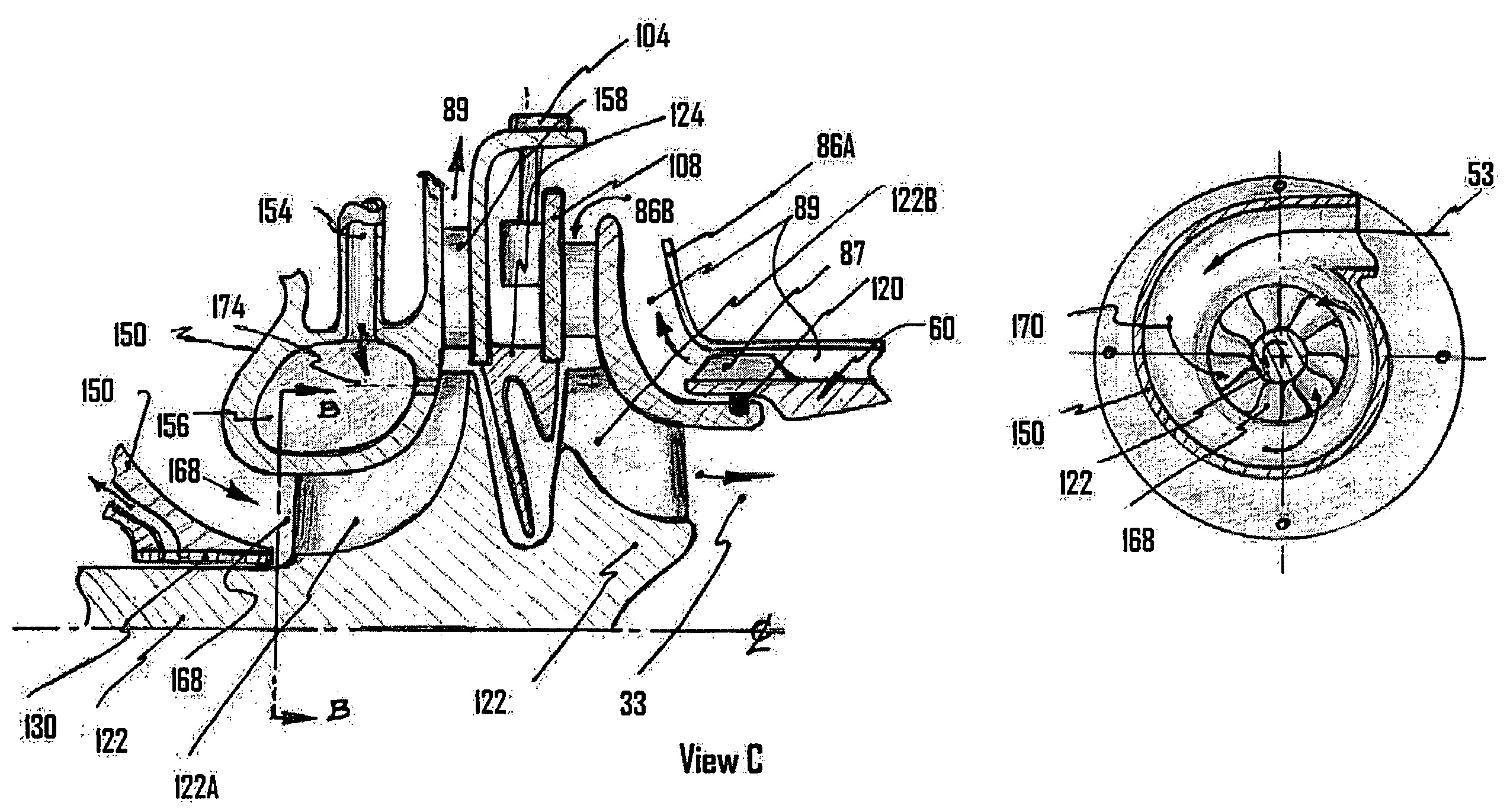
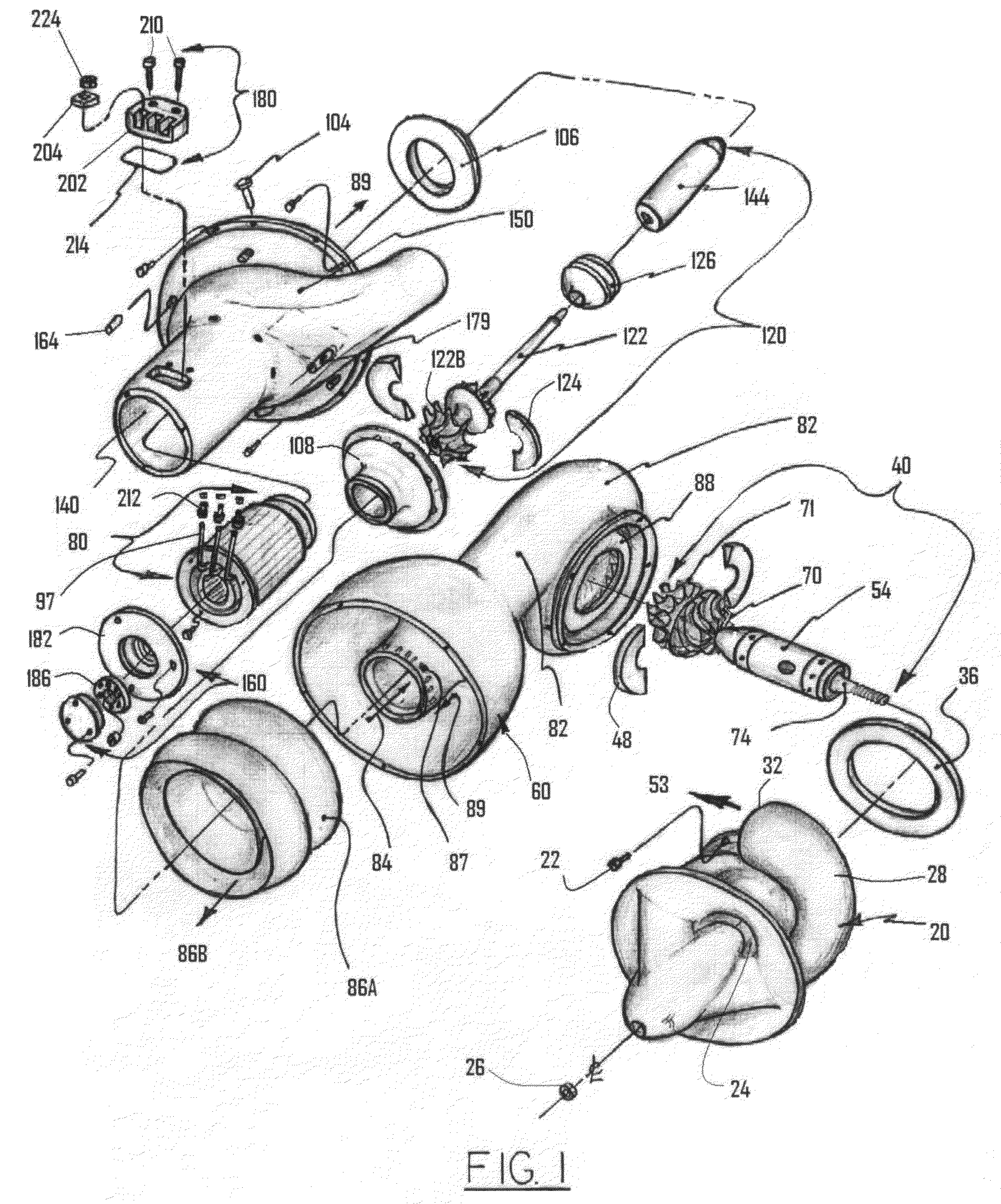
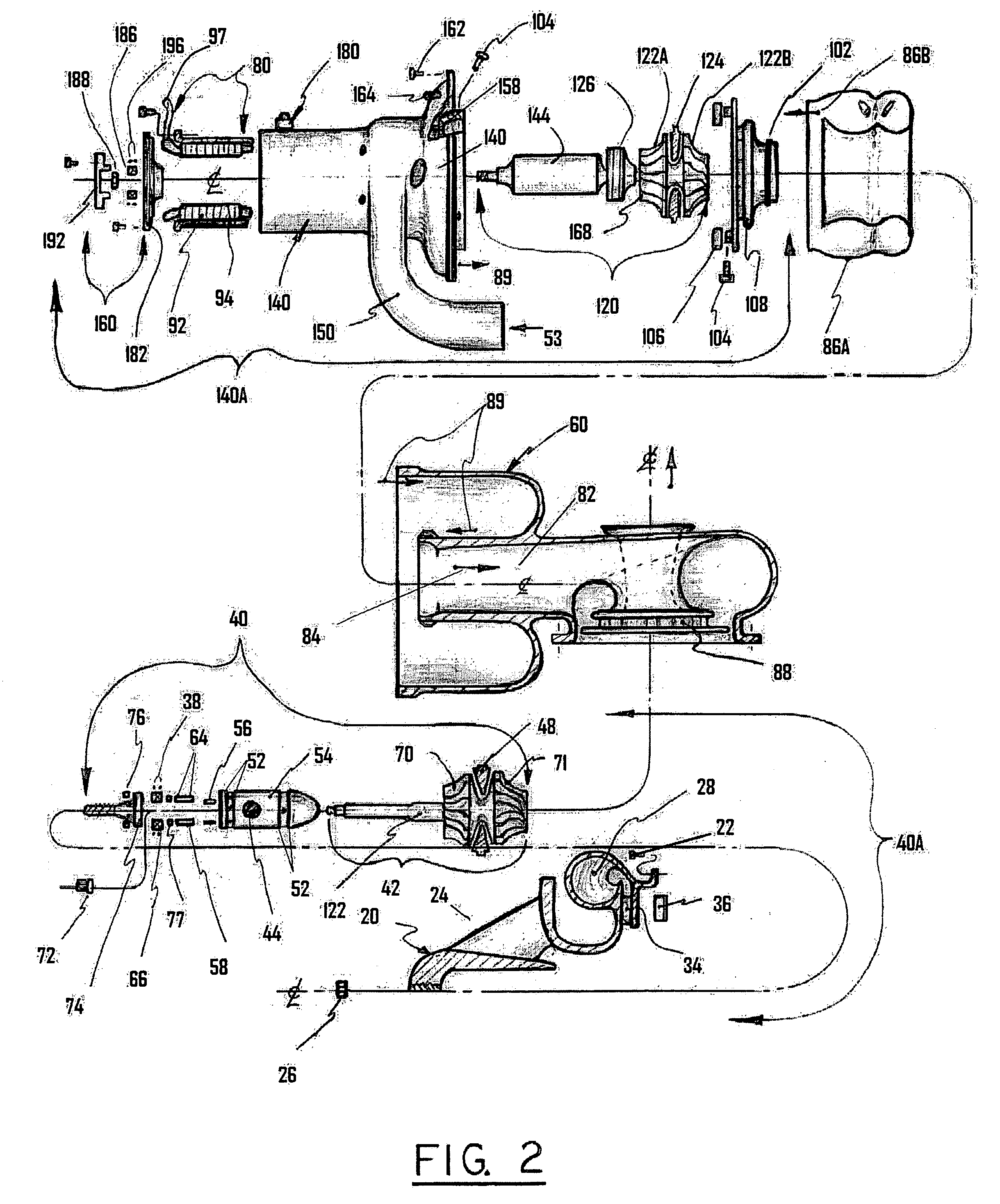
[0045]Turning now descriptively to the drawings, in which similar reference characters denote similar elements throughout the several views, the attached figures illustrate a hybrid microturbine electric power generating system, having two rotor spools, one as a turbo charger, the 2nd rotor spool with an integral alternator all of which are housed electrical stator coaxially positioned about this rotor to create electrical power.

[0046]The 2nd rotor spool assembly and electrical stator assembly with cooling sleeve and electrical power out leads are retained in the #2 housing along with the 2nd compressor diffuser and 2nd turbine nozzle. The #1 spool module communicates with the #2 compressor inlet and as a turbo charger creates compressed air / working fluid and is positioned in the #1 housing with a compressor diffuser and turbine nozzle. The combustor housing attaches to the #1 and #2 spool housing modules and combustor where fuel is supplied to develop heat energy to drive the 1st a...


PUM


Abstract

A hybrid microturbine to produce electrical output power within a engine housing, having a combustor, and a two spool multi stage compressor wherein the 1st spool has a compressor rotor and a turbine rotor as a turbocharger and the 2nd rotor spool has an alternator rotor integrated with a compressor rotor and turbine rotor. The two individual compressor rotors have rotating blades attached and located in compressor housings with fluid communication. The alternator rotor as part of the 2nd spool has permanent magnets integrated and positioned in close proximity and co-axial to the electrical stator module having an iron laminated structure with electrical wires. Relative rotational motion between the stator and alternator rotor cause electricity to be generated.

Description

[0001]This application claims benefit of provisional application of Ser. No. 60 / 459,861 filed Apr. 2, 2003.BACKGROUND OF THE INVENTION[0002]1. Field of the Invention[0003]This invention relates to a hybrid microturbine engine having a 1st and 2nd rotor spool and a turbo charged multistage compressor system where one rotor spool incorporates a turbine and compressor as the turbo charger and the 2nd spool having a turbine, compressor, and an alternator rotor in close proximity and co-axially within a laminated iron base stator having wires to generate electricity.[0004]2. Description of Prior Art[0005]It can be appreciated that microturbine devices have been in use for years. Typically, a microturbine device is comprised of a single rotor spool with integral alternator attached and used in distributed electrical power generation. Companies include Elliott Energy Systems (EES), Turbec, Honeywell (some development effort only then bought out by GE) and Capstone with a wrap around heat e...

Claims


Application Information

Patent Timeline
Patent Type & Authority Patents(United States)
IPC IPC(8): F02C3/10F02C3/34F02C7/36
CPCF02C3/34F02C7/36F05D2220/76F05D2220/40
Inventor TEETS, JOSEPH MICHAELTEETS, JON WILLIAM
Owner TEETAB JOSEPH MICHAEL
Why Eureka
Try Eureka