

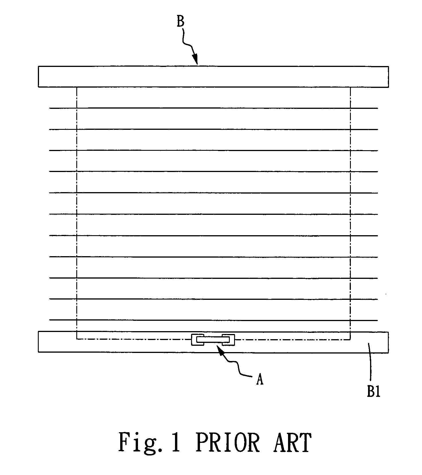
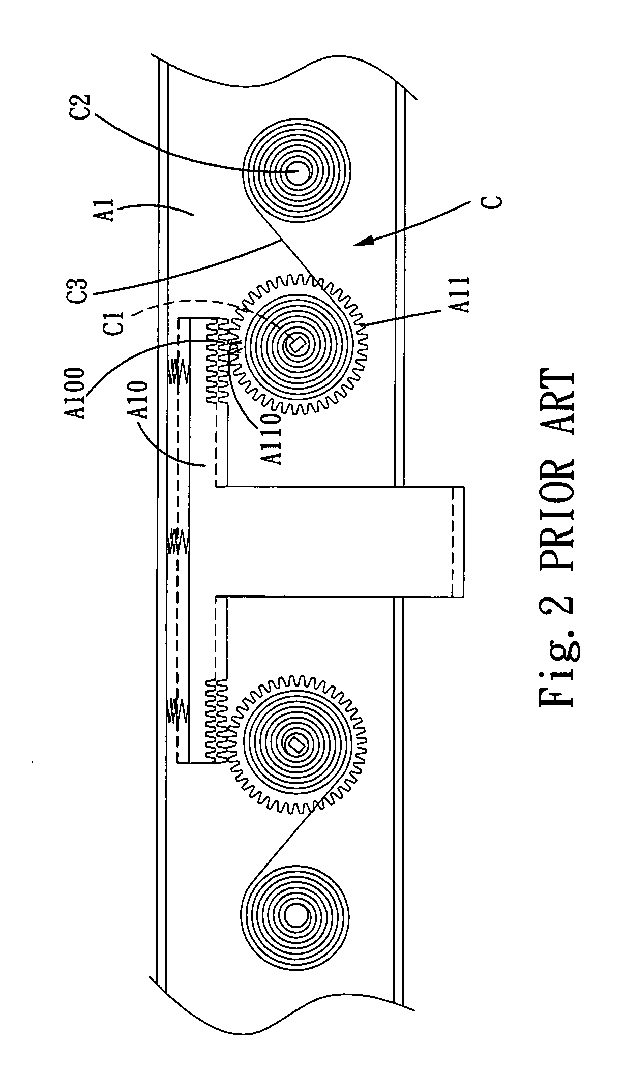
Pulling cord winder for venetian blind
a technology for venetian blinds and winders, which is applied in the direction of shutters/movable grilles, door/window protective devices, wing arrangements, etc., can solve the problems of increasing the overall cost of the assembly, occupying more space, and increasing the lower rail bb>1/b>, so as to reduce the weight, the effect of occupying too much space and incurring too much cos
- Summary
- Abstract
- Description
- Claims
- Application Information
AI Technical Summary
Benefits of technology
Problems solved by technology
Method used
Image

Examples
Embodiment Construction
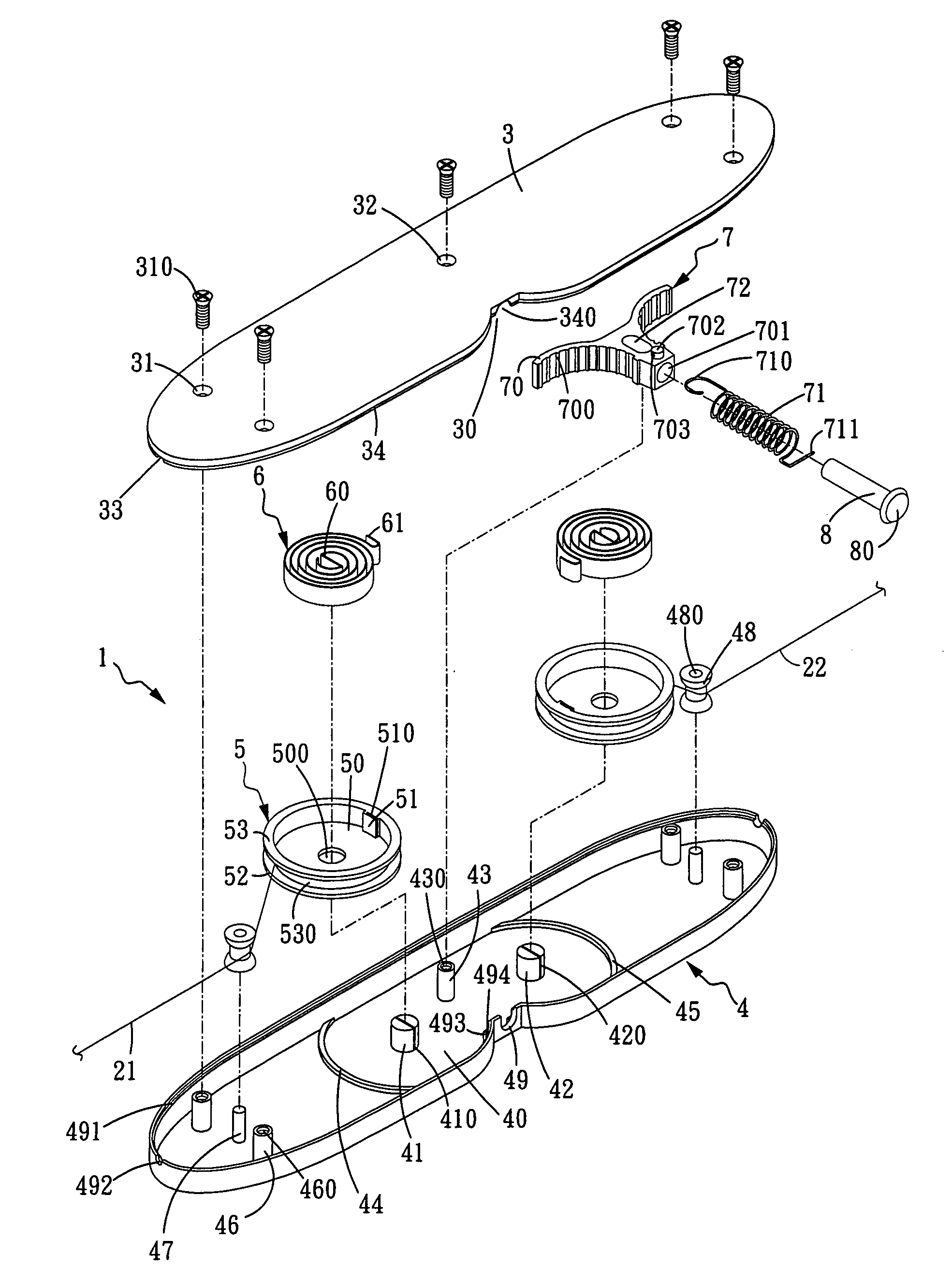
[0026]The basic assembly of a pulling cord winder for a Venetian blind in accordance with the present invention is shown in FIGS. 5 and 6. The pulling cord winder 1 is installed directly at the bottom of a lower rail 20 of a Venetian blind 2, and a pulling cord 21, 22 is disposed separately on both sides of the pulling cord winder 1. The pulling cord winder 1 comprises: an upper base 3 and a lower base 4 engaged with each other, two fixed cams 41, 42; two spring coil wheels 5 mounted onto the fixed cams 41, 42 in a chamber 40 at the center of the lower base 4, and a spring 6 being disposed in each of the spring coil wheels 5 and hooked by both embedding ends 60,61 therein; a brake member 7 placed between the two spring coil wheels 5 and hooked by a drawspring 71; and a push rod 8 passing through the drawspring 71 and contacting the brake member 7, the push rod being pressed to release the brake member and released to apply the brake member, such that when the push rod 8 is released ...
PUM
 Abstract
Description
Claims
Application Information