Remotely resettable ropeless emergency stopping device for an elevator

a technology of emergency stopping and remote resetting, which is applied in the direction of computer control, instruments, etc., can solve the problems of excessive speed of cars, significant number of components that are required to effectively operate the system, and high installation time of sheaves, ropes and governors, so as to reduce equipment costs and installation time, and reduce maintenance. , the effect of speeding up the stop

Active Publication Date: 2009-08-18
OTIS ELEVATOR CO
View PDF17 Cites 74 Cited by
  • Summary
  • Abstract
  • Description
  • Claims
  • Application Information

AI Technical Summary

Benefits of technology

[0012]The subject safety system decreases the equipment costs and installation time. Further, the system requires less maintenance due to fewer cycles and wearing parts, and provides faster stops in high rise applications. The various features and advantages of this invention will become apparent to those skilled in the art from the following detailed description of the currently preferred embodiment. The drawings that accompany the detailed description can be briefly described as follows.

Problems solved by technology

If the hoist ropes break or other elevator operational components fail, causing the elevator car to travel at an excessive speed, the governor then releases a clutch that grips the governor rope.
One disadvantage with this traditional safety system is that the installation of the sheaves, rope, and governor is very time consuming.
Another disadvantage is the significant number of components that are required to effectively operate the system.
The governor sheave assembly, governor rope, and tension sheave assembly are costly and take up a significant amount of space within the hoistway, pit, and machine room.
Also, the operation of the governor rope and sheave assemblies generates a significant amount of noise, which is undesirable.
Further, the high number of components and moving parts increases maintenance costs.

Method used


Image

  • Remotely resettable ropeless emergency stopping device for an elevator
  • Remotely resettable ropeless emergency stopping device for an elevator
  • Remotely resettable ropeless emergency stopping device for an elevator

Examples


Embodiment Construction

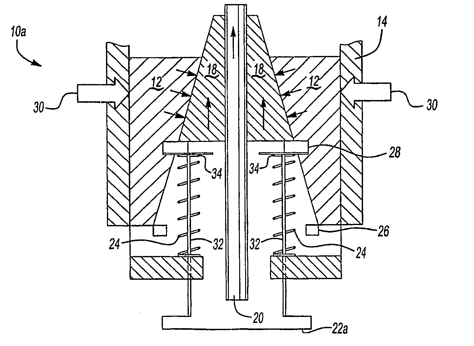
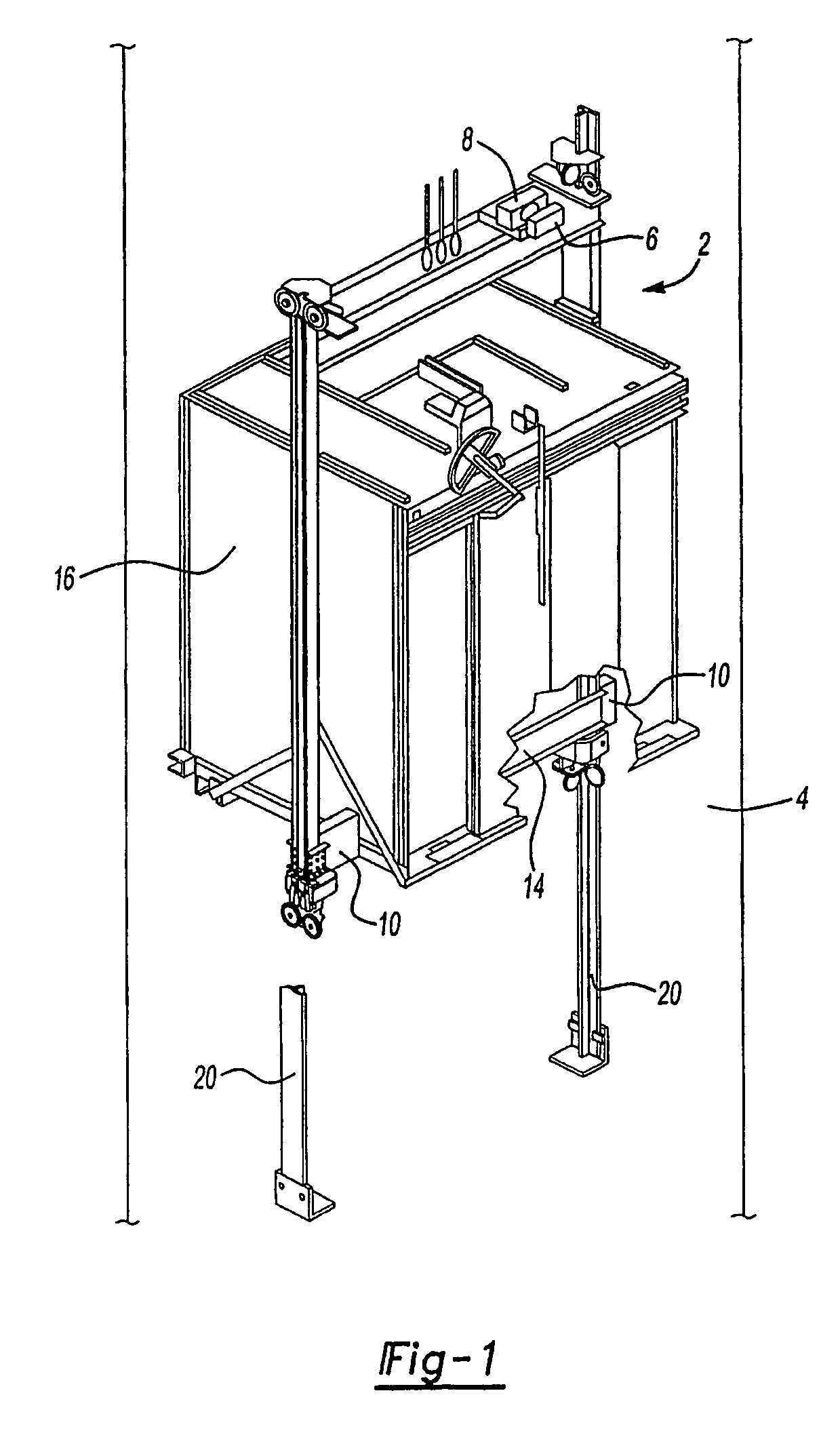
[0022]An elevator assembly 2, shown in FIG. 1, is mounted for movement within a hoistway 4. The elevator assembly 2 includes a speed sensor 6 that continuously measures the speed of the elevator assembly 2. The sensor 6 communicates with an elevator control 8, which generates control signals for controlling movement of the elevator assembly 2. Any type of speed sensor known in the art could be used to monitor elevator speed. The control 8 also communicates with an elevator brake system 10. The brake system 10 includes a unique configuration that can be incorporated into various different types of elevator brakes. In one example, the elevator brake system 10 comprises an elevator safety brake system that stops the elevator 2 from traveling at excessive speeds.

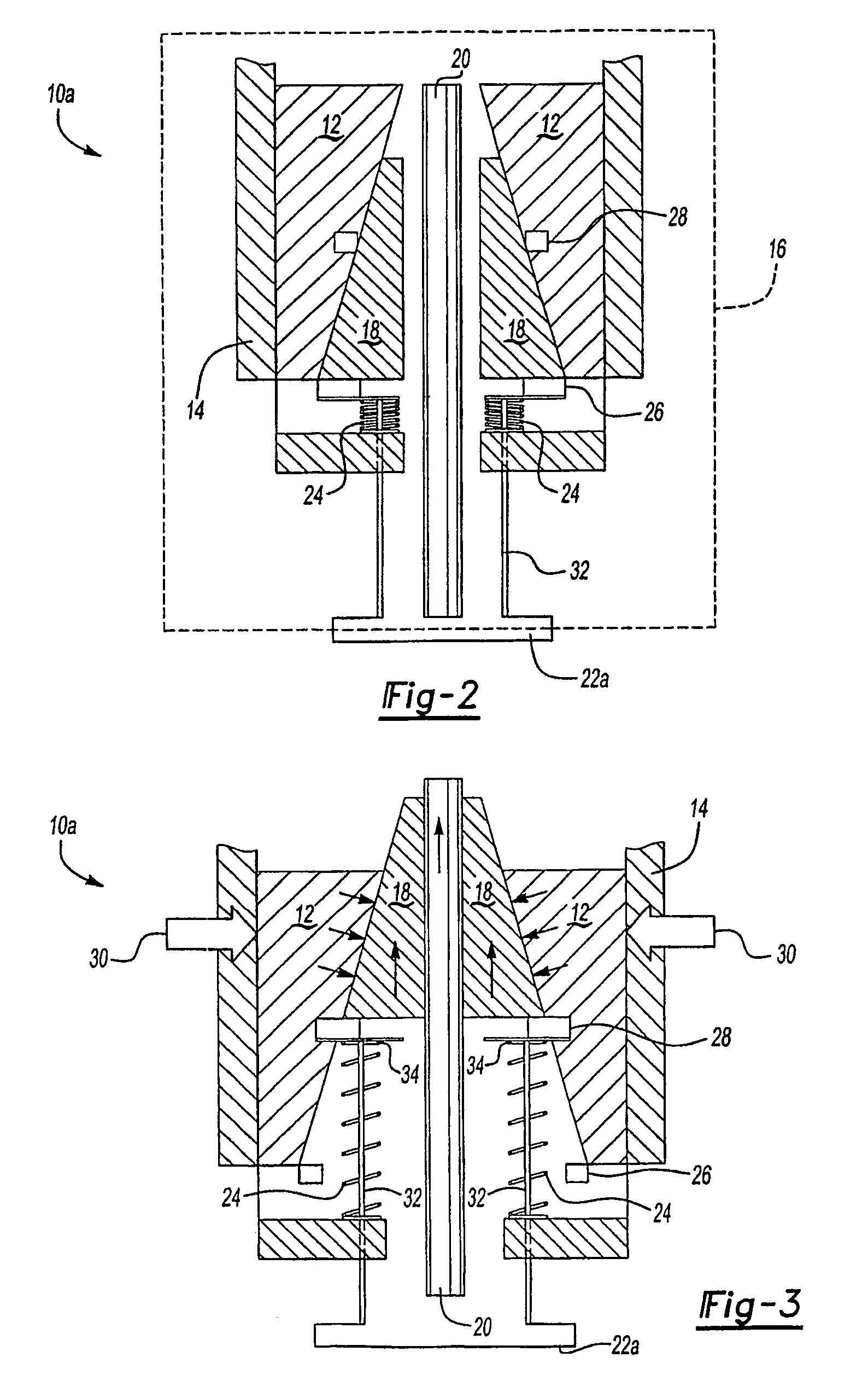
[0023]As seen in FIG. 2, one example of the elevator safety brake system is shown generally at 10a. The elevator safety brake system 10a includes a safety housing 12 that is connected to an elevator car frame 14. Thus, movement ...


PUM


Abstract

A brake mechanism (10) for an elevator (2) is activated in response to an electronic control signal to prevent movement of an elevator car (16) under predetermined conditions. The brake mechanism is preferably a safety mechanism (10) and does not require a governor sheave, a governor rope, or a tension sheave. The safety mechanism in one disclosed example utilizes a solenoid actuator (22b) and an electric motor (40) and gear box assembly (42) to move safety wedges (18) into engagement with a guide rail (20) to stop the elevator car (16). The safety wedges (18) are held in a non-deployed position during normal elevator operation. If there is a power loss or if elevator car speed exceeds a predetermined threshold, an electronic control signal activates the safety mechanism (10) causing the solenoid to release, which causes the safety wedges (18) move in a direction opposite to that of a safety housing (12) mounted for movement with the elevator car (16). Angled surfaces of the safety housing (12) force the safety wedges (18) into engagement with the guide rail (20). The safety mechanism (10) can be selectively reset from a remote location.

Description

FIELD OF THE INVENTION[0001]This invention generally relates to an electrically controlled braking device for an elevator system. More particularly, this invention relates to a ropeless and sheaveless remotely resettable emergency stopping device for an elevator.DESCRIPTION OF THE RELEVANT ART[0002]Elevators include a safety system to stop an elevator from traveling at excessive speeds in response to an elevator component breaking or otherwise becoming inoperative. Traditionally, elevator safety systems include a speed sensing device typically referred to as a governor, a governor rope, safeties or clamping mechanisms that are mounted to the elevator car frame for selectively gripping elevator guide rails, and a tension sheave located in an elevator pit. The governor includes a governor sheave located in a machine room, which is positioned above the elevator. The governor rope is attached to travel with the elevator car and makes a complete loop around the governor sheave and the te...

Claims


Application Information

Patent Timeline
Patent Type & Authority Patents(United States)
IPC IPC(8): B66B5/06B66B5/04B66B5/22
CPCB66B5/22B66B5/06B66B5/04B66B5/02
Inventor OH, JAE-HYUKMILLER, ROBIN MIHEKUNPERUGGI, RICHARD E.WAN, SAMUELCOONEY, ANTHONYBACELLAR, ADRIANAPENG, PEI-YUAN
Owner OTIS ELEVATOR CO
Why Eureka
Try Eureka